Supermini SlimeVR
Tiny, easy, comfy and tough DIY SlimeVR Full Body Trackers - PCB Gerbers, 3D Print Files, Shopping list and guide for assembly
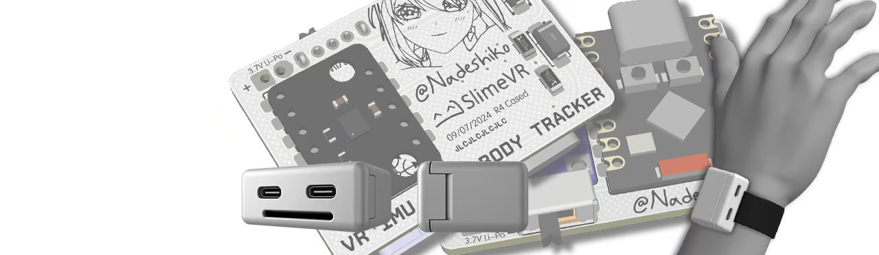
Supermini SlimeVR is a project involving an ESP32-C3 variant PCB, Case CAD, and 3D printing. This tracker is designed to be compact and efficient for VR body tracking.
These are some of the smallest WiFi module based SlimeVR trackers possible, similar to Gorbit99’s Tiny Slime, as small as extension trackers! The idea was for these to be a replacement for wired extension trackers, whose cables can get in the way and are prone to damage, and be a more useable and comfortable size for tracking locations such as shoulders, lower arms, neck, or head.
Due to how small these are, there is no option to connect an extension tracker, as that will only increase the overall size and cost of a whole tracker set.
@Nadeshiko’s Supermini SlimeVRs run on a ESP32-C3 Supermini with an IMU IC of your choice that has the same module profile as widely used SlimeVR IMU-module format like the Mumo ICM-45686’s. They use the TP4056 Unprotected lithium charger module for 3.7V LiPo batteries.
- 2.6cm x 3.8cm PCB design.
- Easy and very cheap to build.
- No wires needed to be soldered.
- Lightweight and smooth, clean case looks.
- 25mm strap width is supported.
Index
Project Sections
PCB
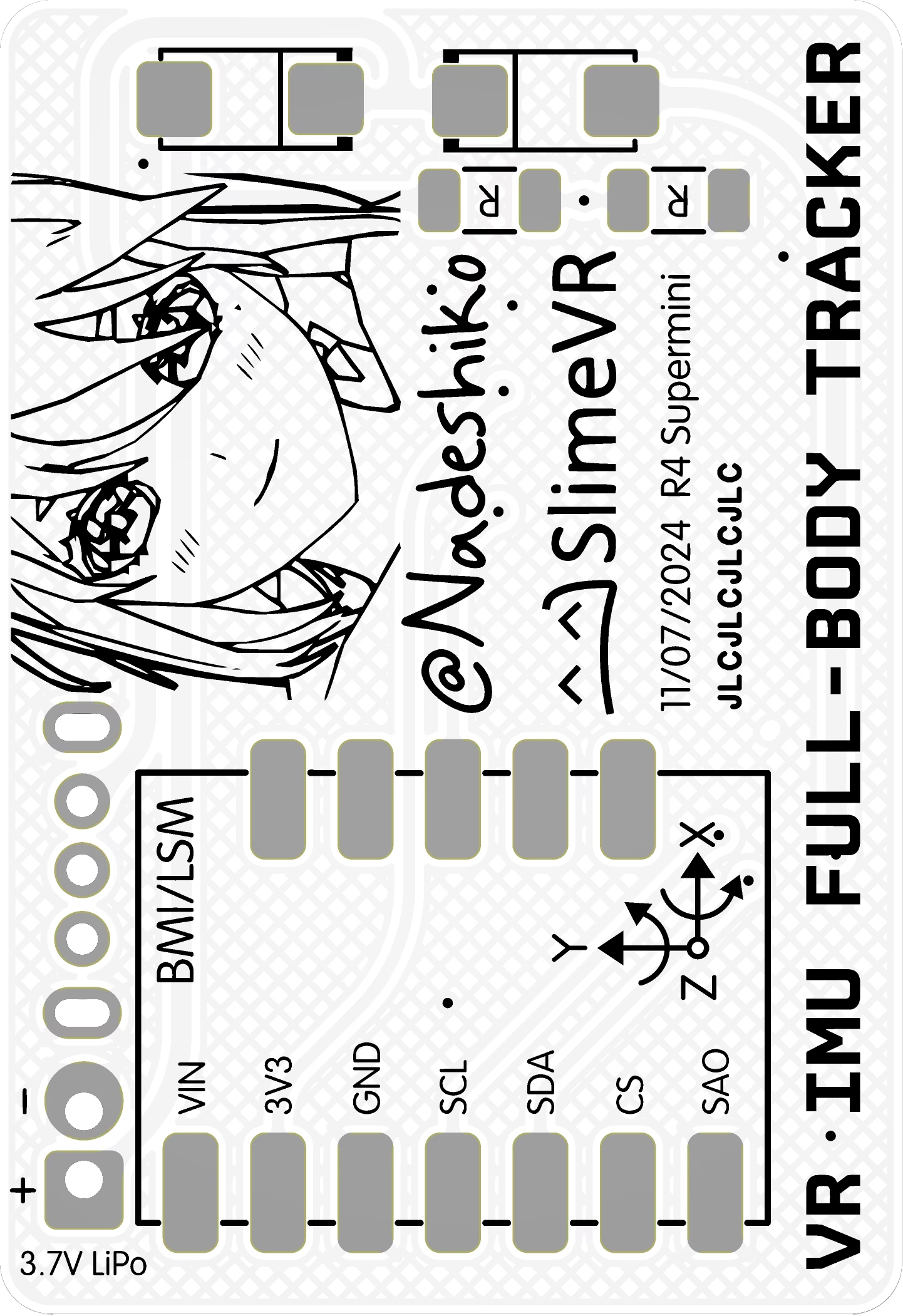
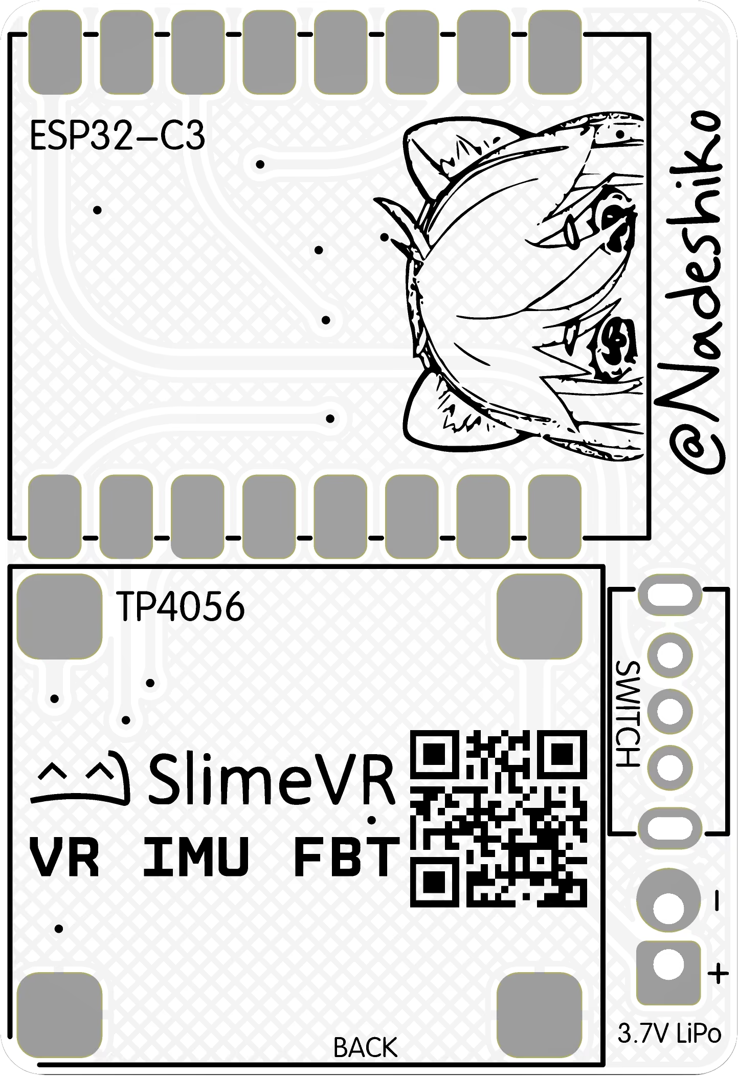
The PCB lets every component be soldered on without any wire connections between the modules. This includes the diodes and resistors for battery sense and charge protection. The ESP32-C3 Supermini is on the back side to save on size and cost; a JST 2mm 2-pin connector can be added to make battery connections easier; an SK12D07VG 3-pin switch will be used to turn the tracker on or off.
PCBs can be ordered from JLCPCB, Elecrow, PCBGOGO, NextPCB or your preferred low cost PCB manufacturer.
Cases
The standard tracker case can house a 3.7V LiPo with Max LiPo cell dimensions 6x25x40mm, a 602535 or similar LiPo is recommended. There is also a double/taller battery variant of the case which allows stacking two batteries in parallel or a thick LiPo for longer runtime, this case is 5.6mm taller allowing LiPo cells to be 12mm tall.
The cases has been designed according to JLCPCB/JLC3DP resin 3D printing guidelines. The case can be ordered from JLC3DP or Elecrow, and the resin to select on your order is up to you. I prefer the 9000R, CBY, Black Resin, or equivalent low cost options..
It prints as two parts: a snap-fit closure with holes for strap, the TP4056 charger and ESP32-C3 USB ports, and the power switch.
25mm strap can be fitted to the cases; the best one to use is the non-slip elastic kind with plastic buckles and tri-buckles in the same size to make it easier to remove, more comfortable and adjustable. Hook and Loop style of strap can also be used.
The files for the standard case are:

The files for the double stack battery case are:

Components
The component cost should come out to around £8/€9/$11 per tracker with the recommended ICM-45686 IMUs. Quantity and prices listed below are per tracker expense and quantity used of each component. Some of the smaller items are sold in pack sizes of 10/50/100 etc. which can build multiple trackers with. Prices here are listed without any shipping costs, or pack sizes, or taxes, and may not be latest.
| Components per SlimeVR Tracker | QTY | £ | Link |
|---|---|---|---|
| @Nadeshiko Mini PCB | 1 | 0.39 | JLCPCB |
| @Nadeshiko Mini Case | 1 | 0.55 | JLC3DP |
| ESP32-C3 SuperMini V1/V2 | 1 | 1.59 | AliExpress |
| SlimeVR Mumo ICM-45686 IMU Module | 1 | 5.00 | SlimeVR |
| TP4056 Unprotected Charger Type-C | 1 | 0.11 | AliExpress |
| SK12D07VG Slide Switch in 3/4/5mm | 1 | 0.04 | AliExpress |
| 1206/3216 Resistors in 100K Ohm | 2 | 0.01 | AliExpress |
| SS34 DO214AC Diodes | 2 | 0.01 | AliExpress |
| LiPo Battery 6x25x40mm or smaller | 1 | 0.72 | EHAO or XINJ or ROGRAPO @AliExpress |
| Mounting Straps for Trackers | Link |
|---|---|
| 25mm Hook & Loop | AliExpress |
| 25mm Elastic Strap & Buckles | AliExpress |
| 25mm Tri Glide Adjustable Buckles | AliExpress |
| 25mm Release Buckles | AliExpress |
Assembly
Using a solder helping hand will make putting everything on the PCB much easier! While soldering, keep your solder iron’s tip tinned with solder when not in use to protect from oxidation. Use plenty of flux for surface mounts. Clean the PCBs from excess flux after soldering and testing, you can use PCB cleaner, isopropyl alcohol, acetone or nail varnish remover.
The basic steps of assembly for the main trackers are:
- 2x 1206 100K resistor and 2x SS34 diodes soldered in the correct orientation on the PCB.
- Solder an unprotected TP4056 charger flush to the PCB.
- Solder on a SK12D07VG slide switch.
- Solder the IMU module to the PCB.
- Solder the ESP32-C3 Supermini module flush to the PCB.
- Solder on the LiPo battery with the power switch in the OFF position in correct polarity.
Flashing:
- Power switch still in the OFF position; Flash firmware using the SlimeVR server or VSCode.
- When flashing, you want to choose
BOARD_LOLIN_C3_MINIas the board. - In Advanced options, change SDA Pin to
"6", SCL Pin to"7", INT Pin to"5"and LED Pin to"8". - In Battery Sense section, select
BAT_EXTERNAL, Shield Resistance to0, Battery Shield R1 & R2 to100kOhm, Battery Sense Pin to1. - OPTIONAL: Use polyimide tape or equivalent on sharp corners and the LiPo battery to protect it from puncture.
- OPTIONAL: Remove the C3 chip antenna and add 29 to 31mm tinned wire for better WiFi signal (20-30dB better signal strength).
TIP
When soldering make sure to use correct iron temperatures, a high quality flux cored solder wire and liquid flux in syringe. A multimeter will come extremely handy to test each component and solder joints. Check some guides on YouTube first if you’ve never soldered before!
Detailed-Assembly
Detailed Assembly Steps
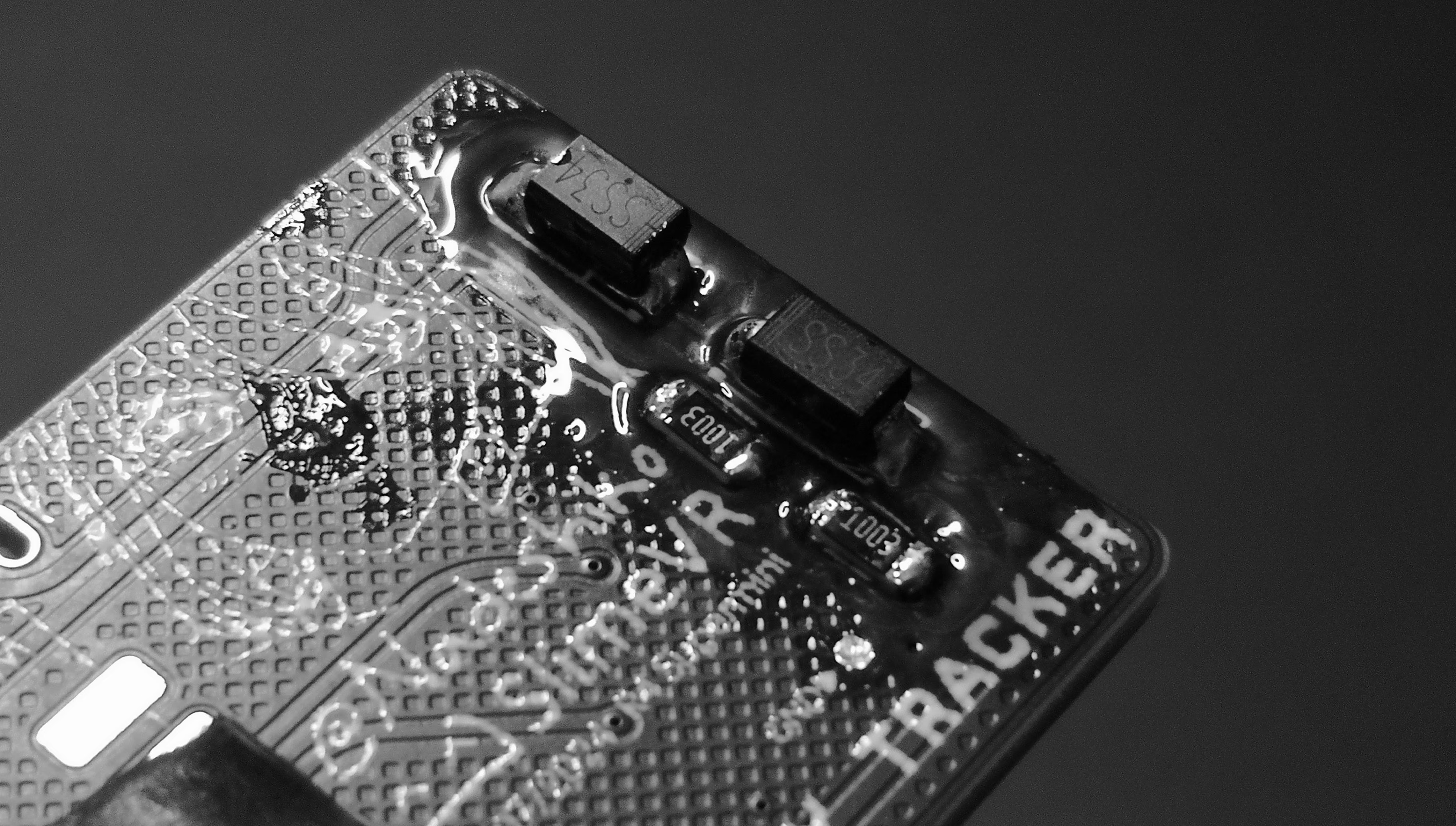
Step 1 - Resistors and Diodes
The diodes have an orientation marked by lines, which will match the line on the PCB diode footprint.
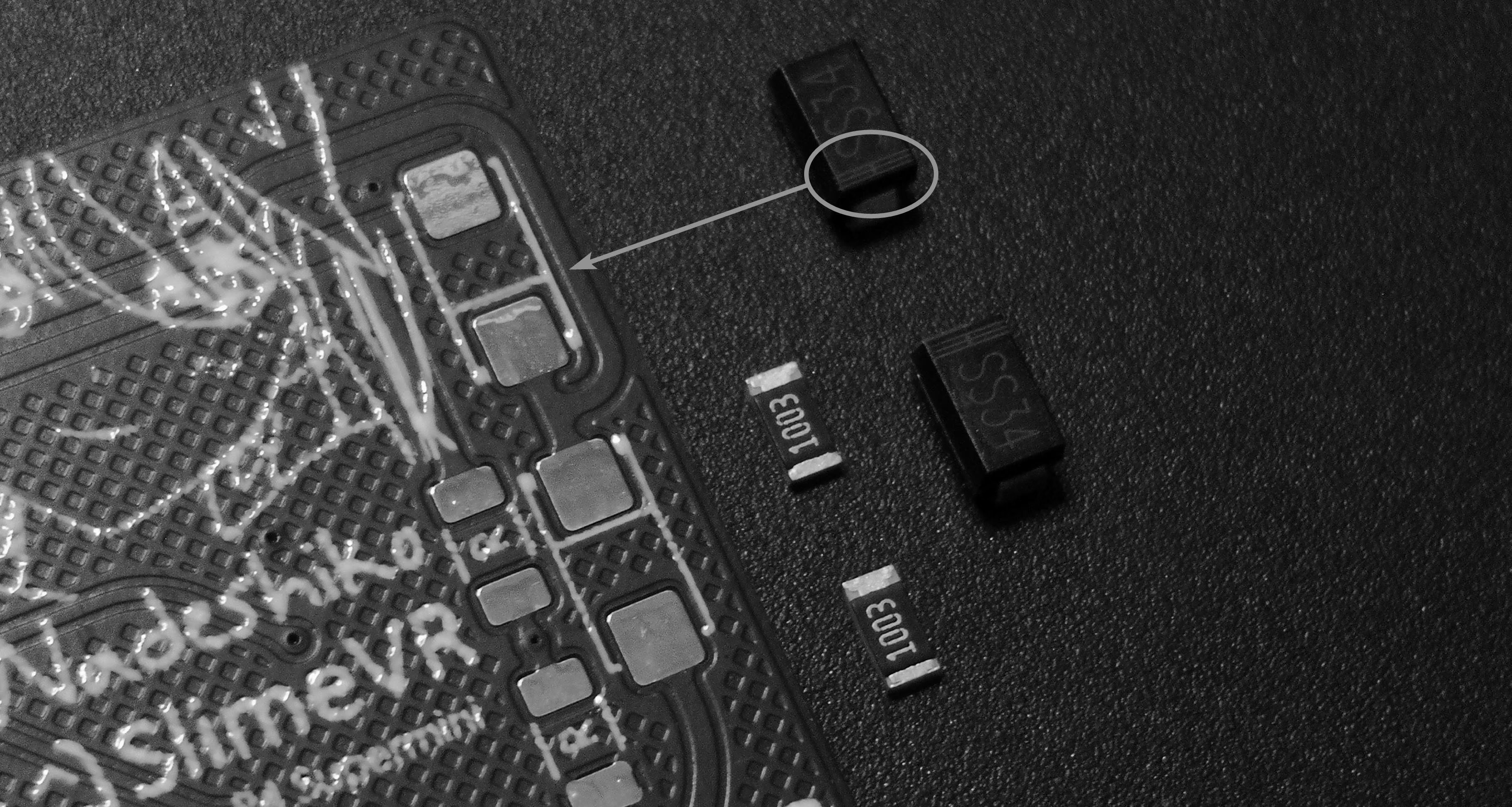
Solder on the 100K resistors first, any orientation. Flux to make them easier to solder as it helps hold them and easier to clean later.
Add a smidge of solder on one of each of the diodes pads, so it can be the first pad to solder the diodes down to.
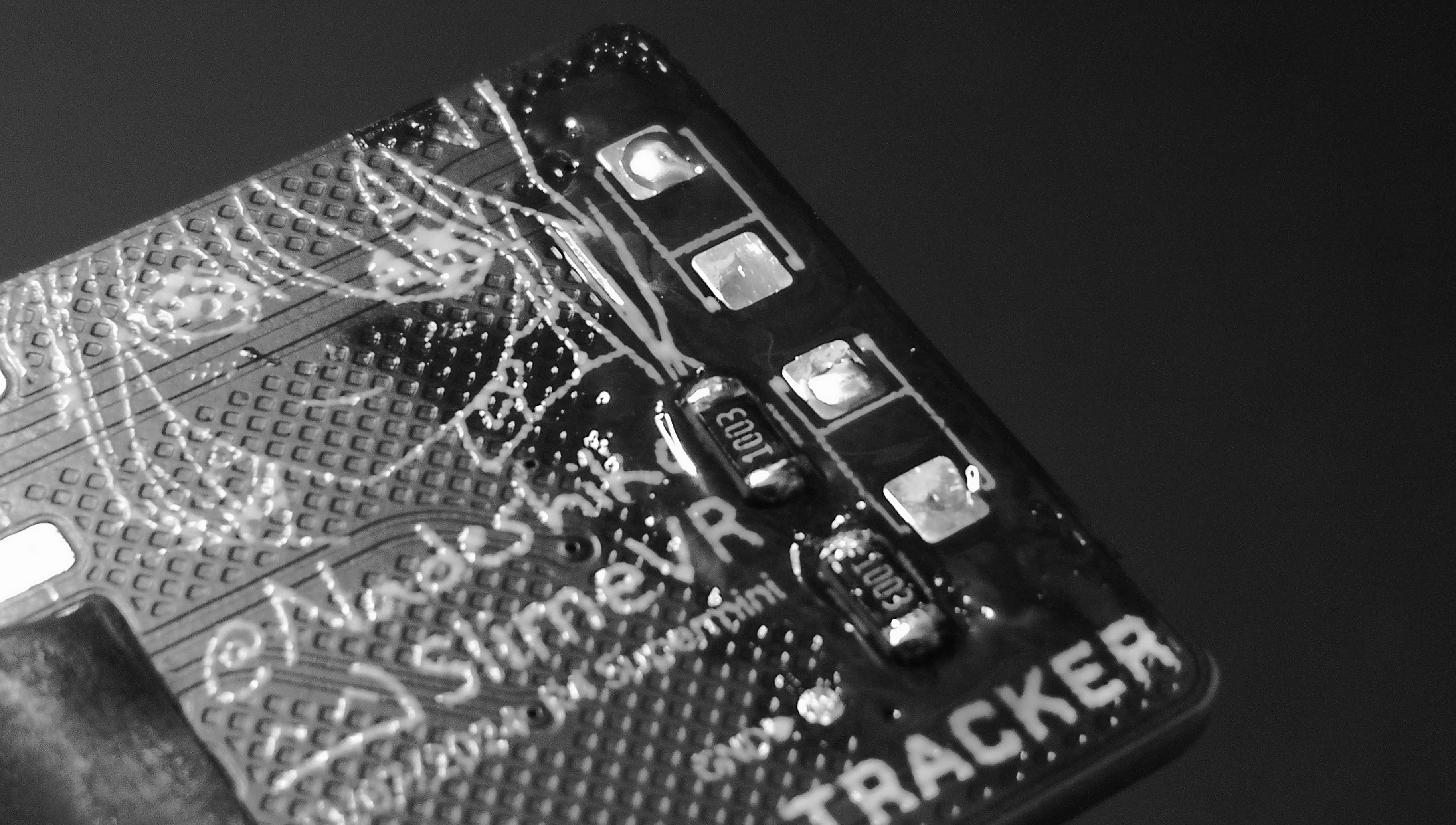
Should look like this, with the diodes lines facing each other:
Step 2 - IMU Module
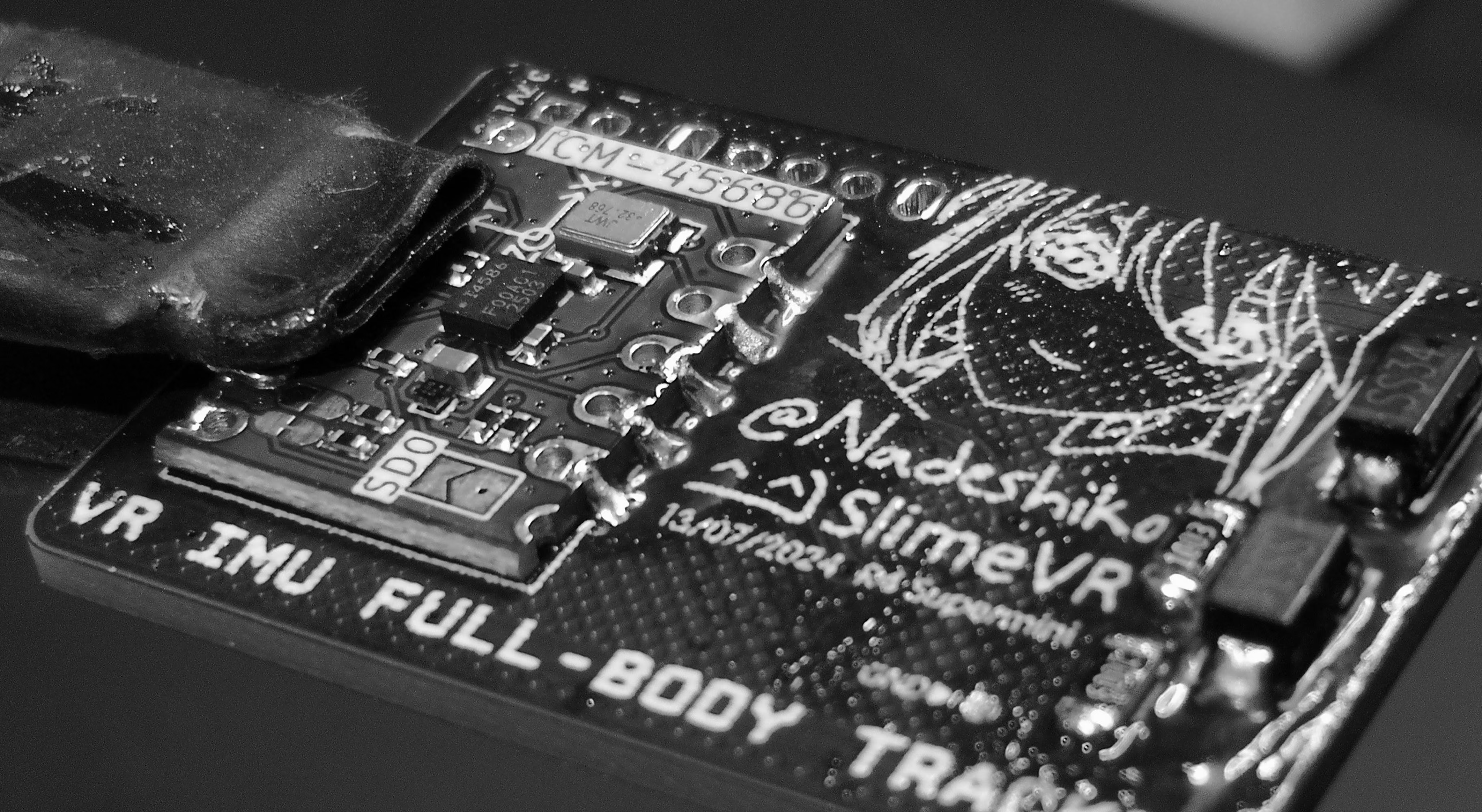
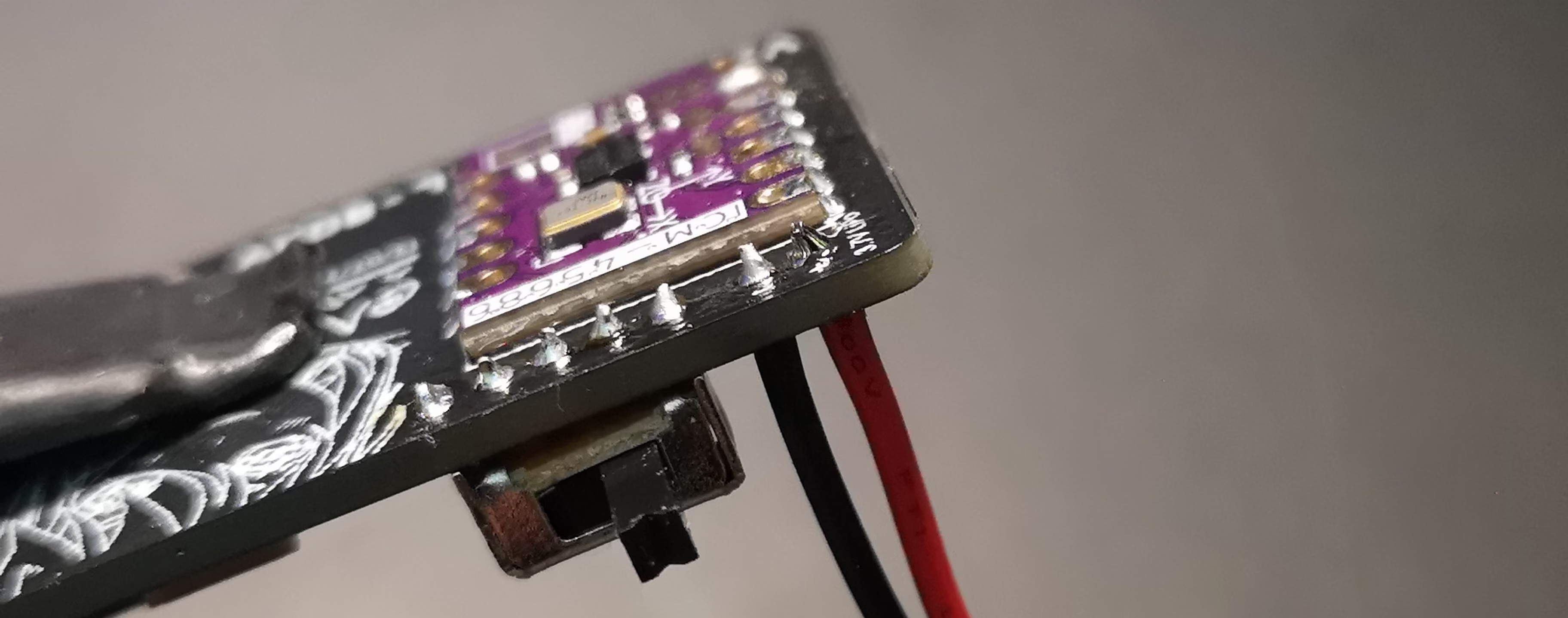
I’m using the Mumo ICM45686 IMU module here from the SlimeVR store, clamp it down on the backside of the PCB where you did the resistor/diodes with your solder helper clamps. I’ve added tiny bit of flux on the pads before doing this too:
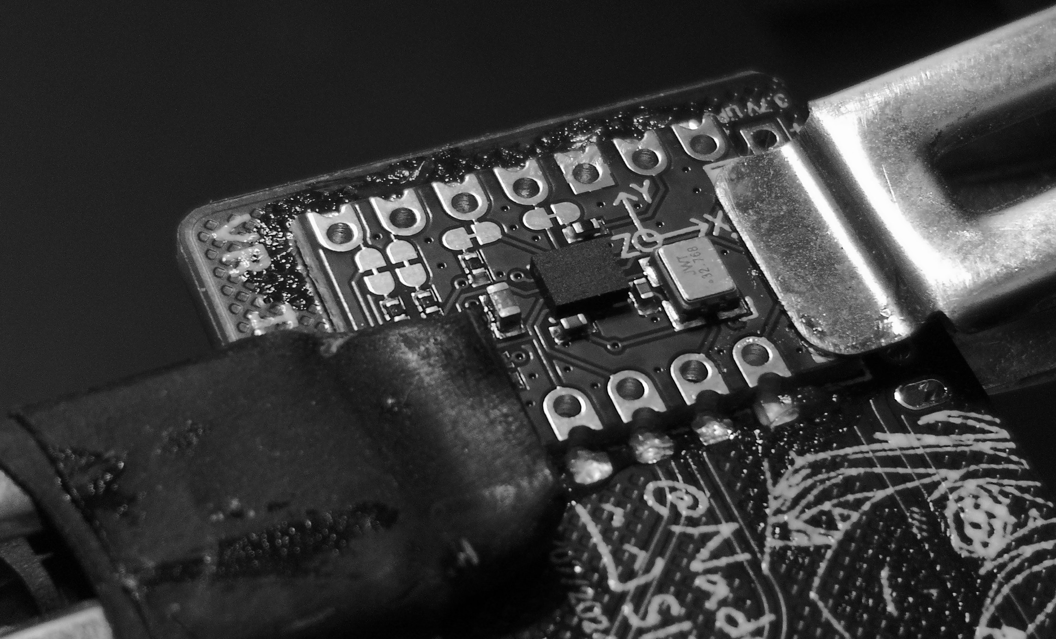
Solder the edge castellated holes of the IMU. If your module of choice does not have those and has drill holes, just use a bit more flux and do the holes instead.
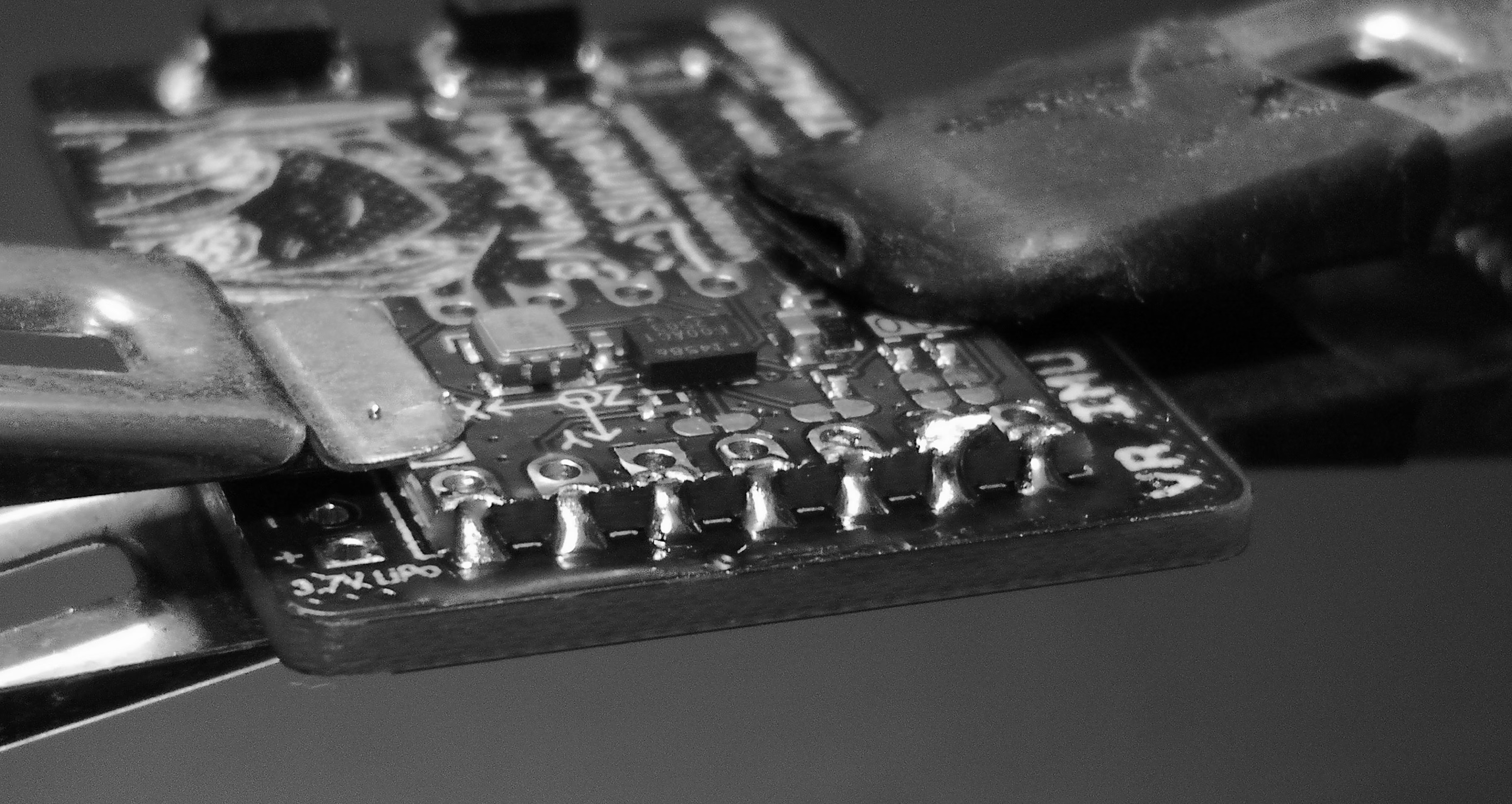
Do both left and right side, and double check visually to make sure there aren’t any missed.
Step 3 - Power Switch
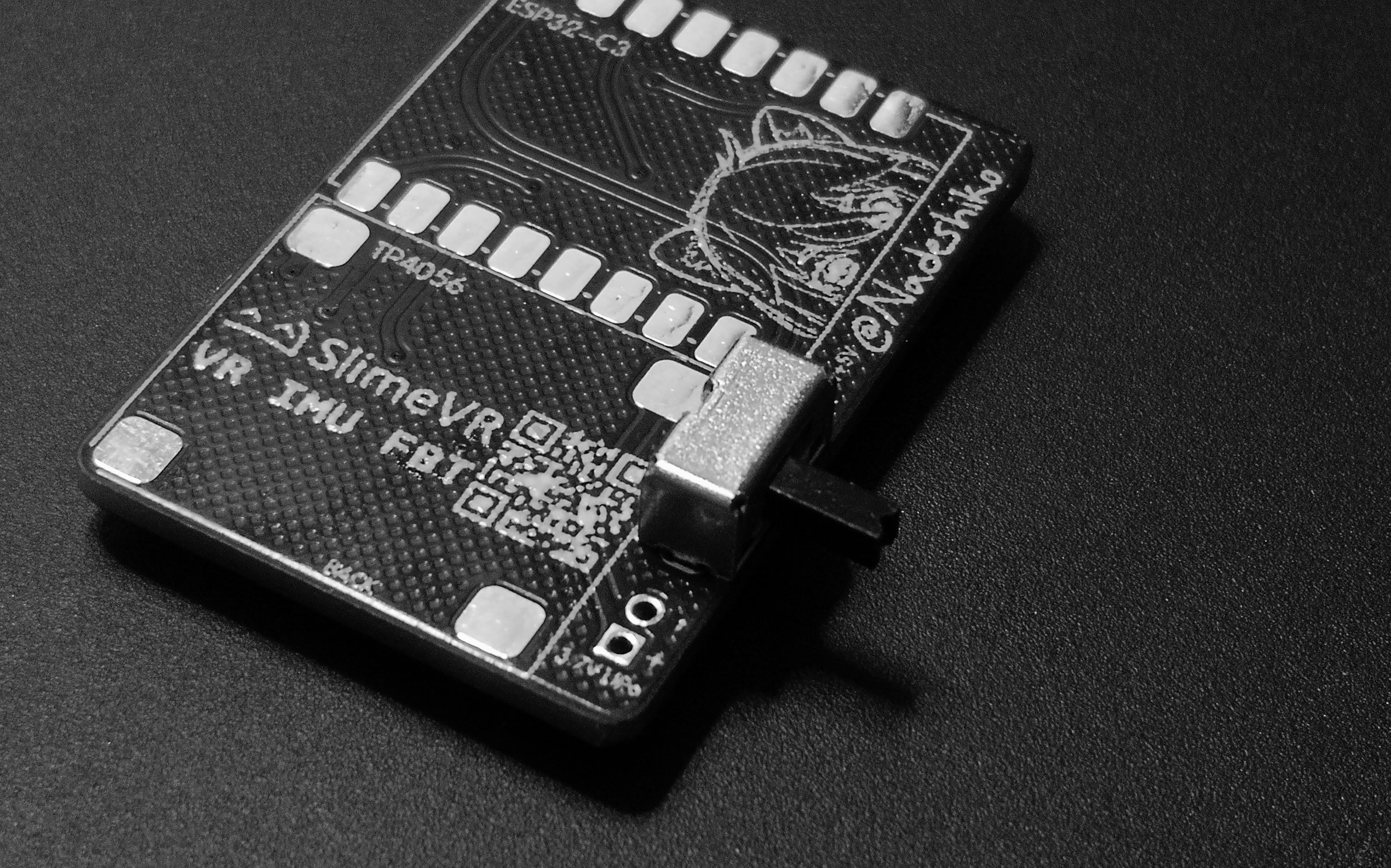
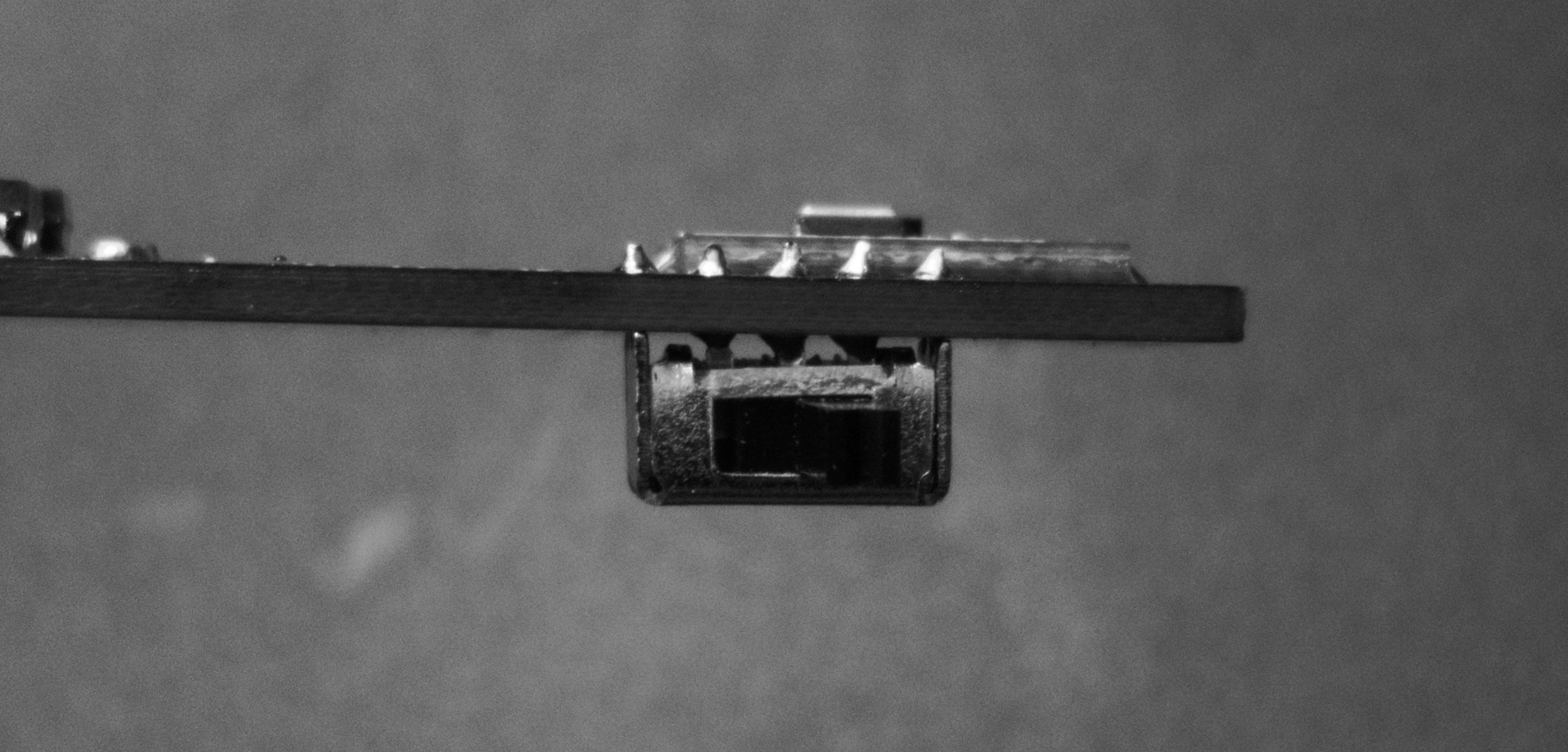
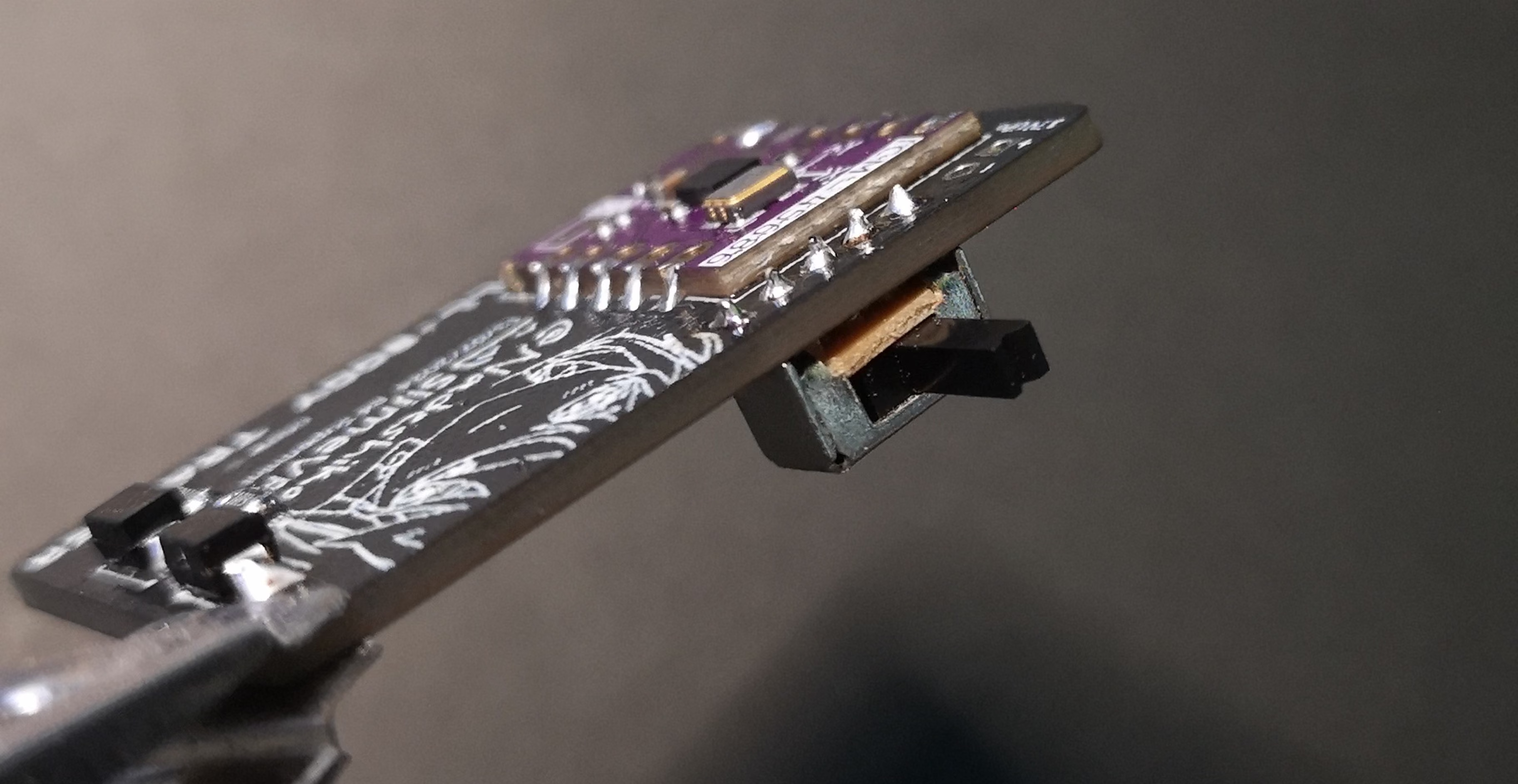
The switch goes on the other side like shown in the image. It has its footprint there.
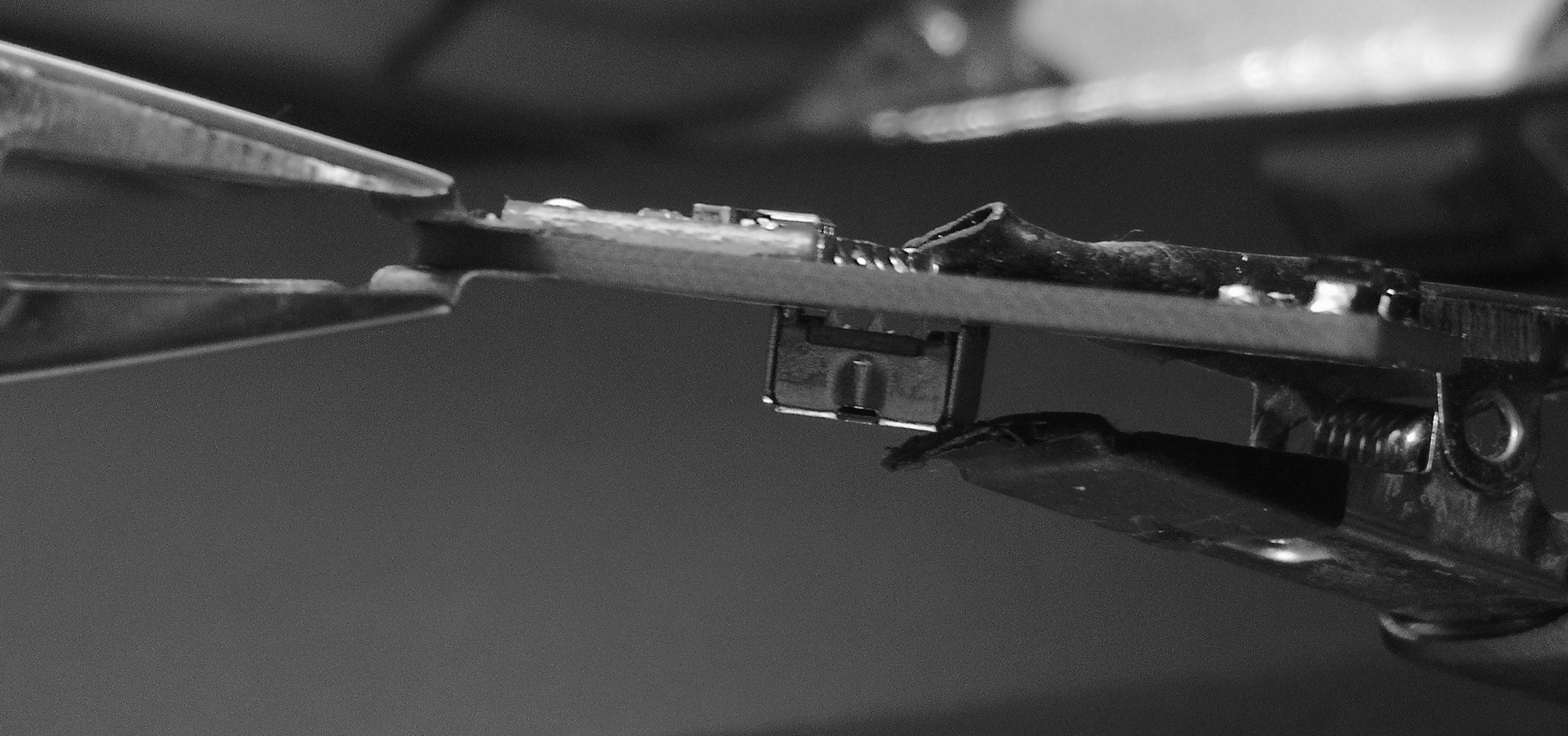
Clamp it flat to the PCB, but still have access to at least one of the legs on the backside of the PCB to solder initially.
Flux those legs/pins and solder.
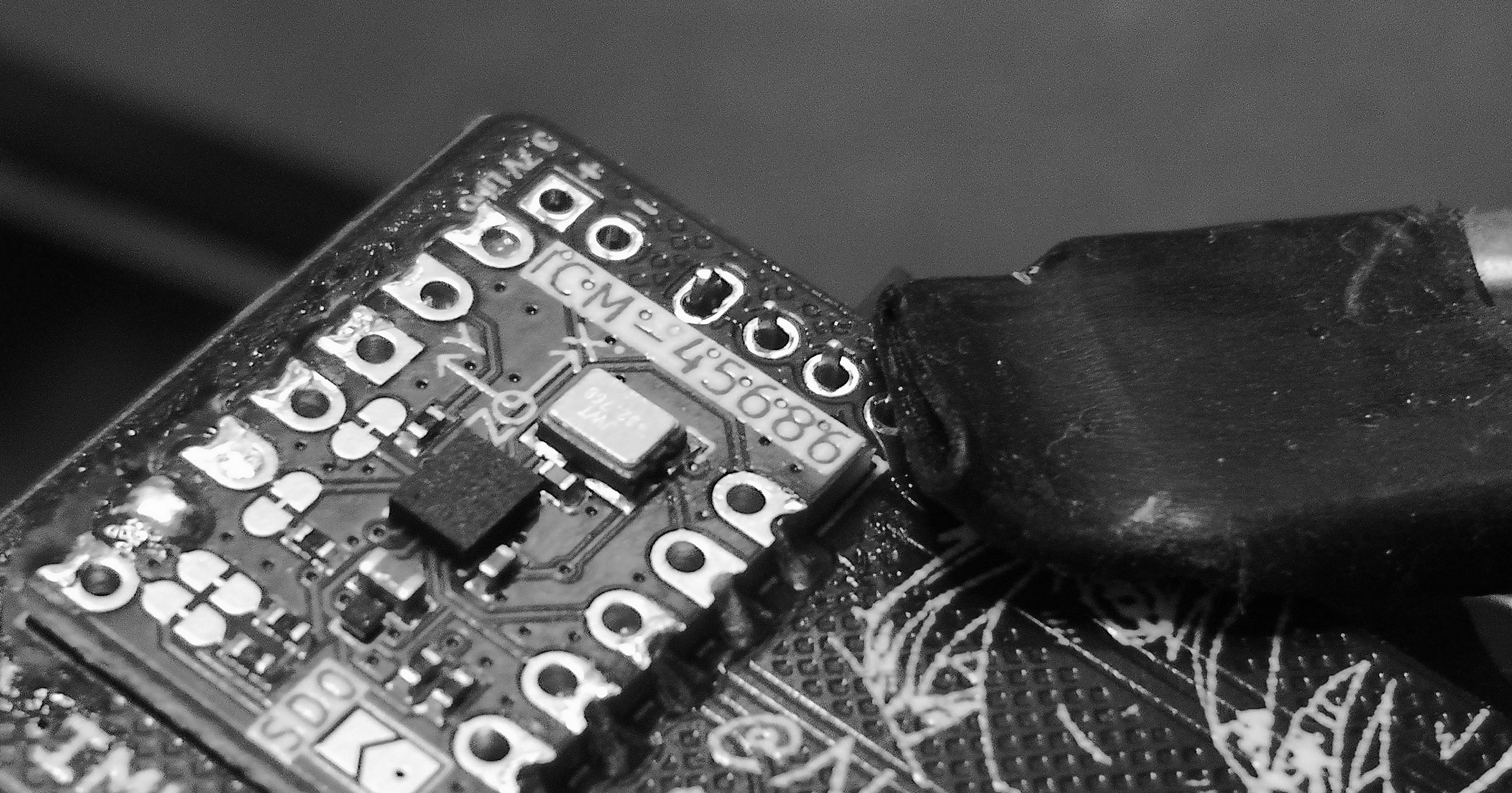
Flux will help pull solder through to the other side, which will make the switch very sturdy:
That does the backside of the PCB, you can clean the excess flux so its not sticky n ewwee for the rest of steps.
Step 4 - ESP32-C3 Supermini Module
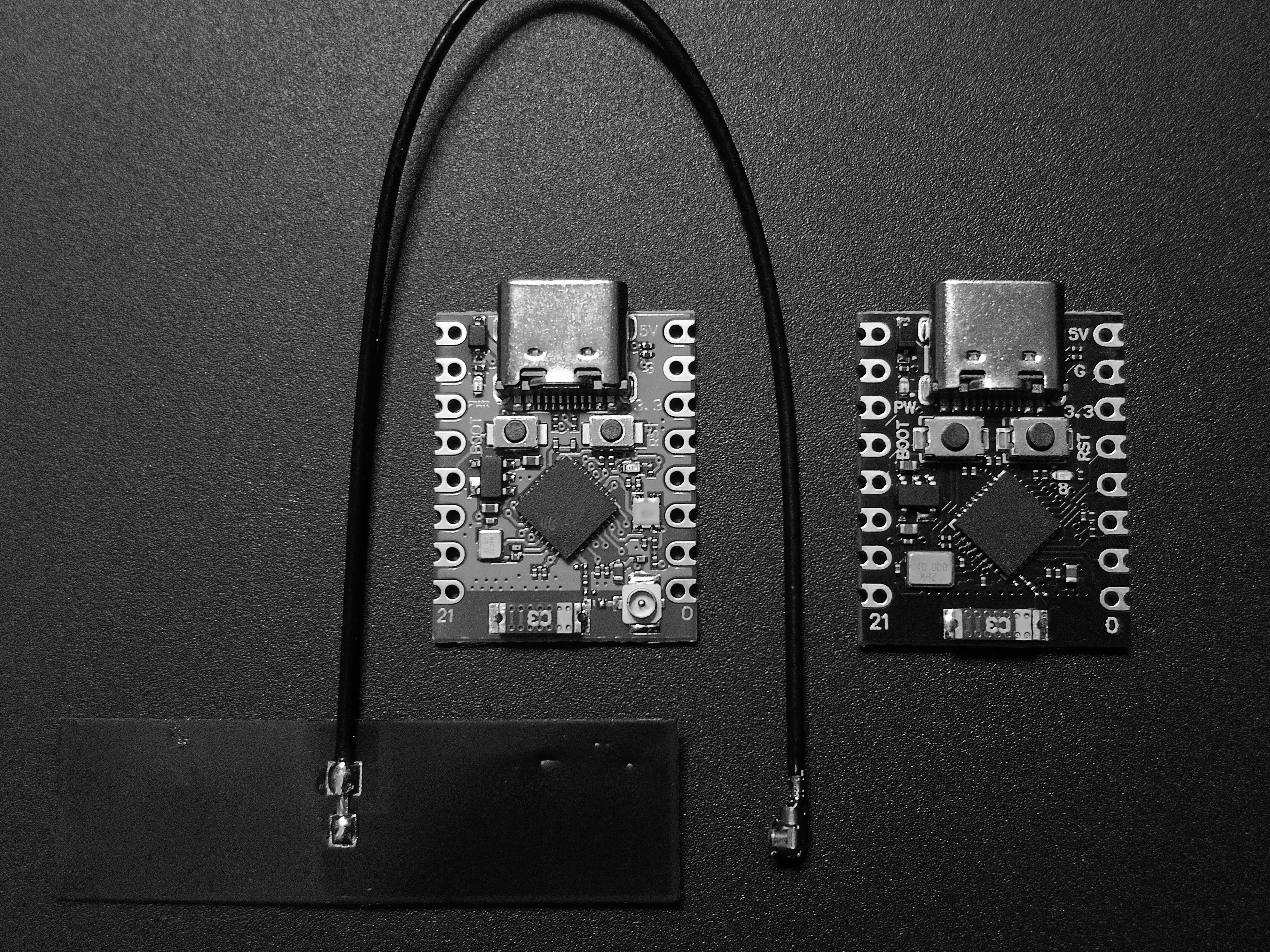
There are few a Supermini C3 variants out there. The most common of these is the one on the right with the C3 antenna only which works perfectly for these slimes. For this guide, I’m using an C3 Supermini Plus which has the same footprint profile as the normal C3 Supermini, but has an flexible IPEX antenna included with it for improved range. I will also explain later on how to use the IPEX antenna properly on the Plus as it requires a small modification for it to work, or how to modify the non IPEX ones for better signal strength.
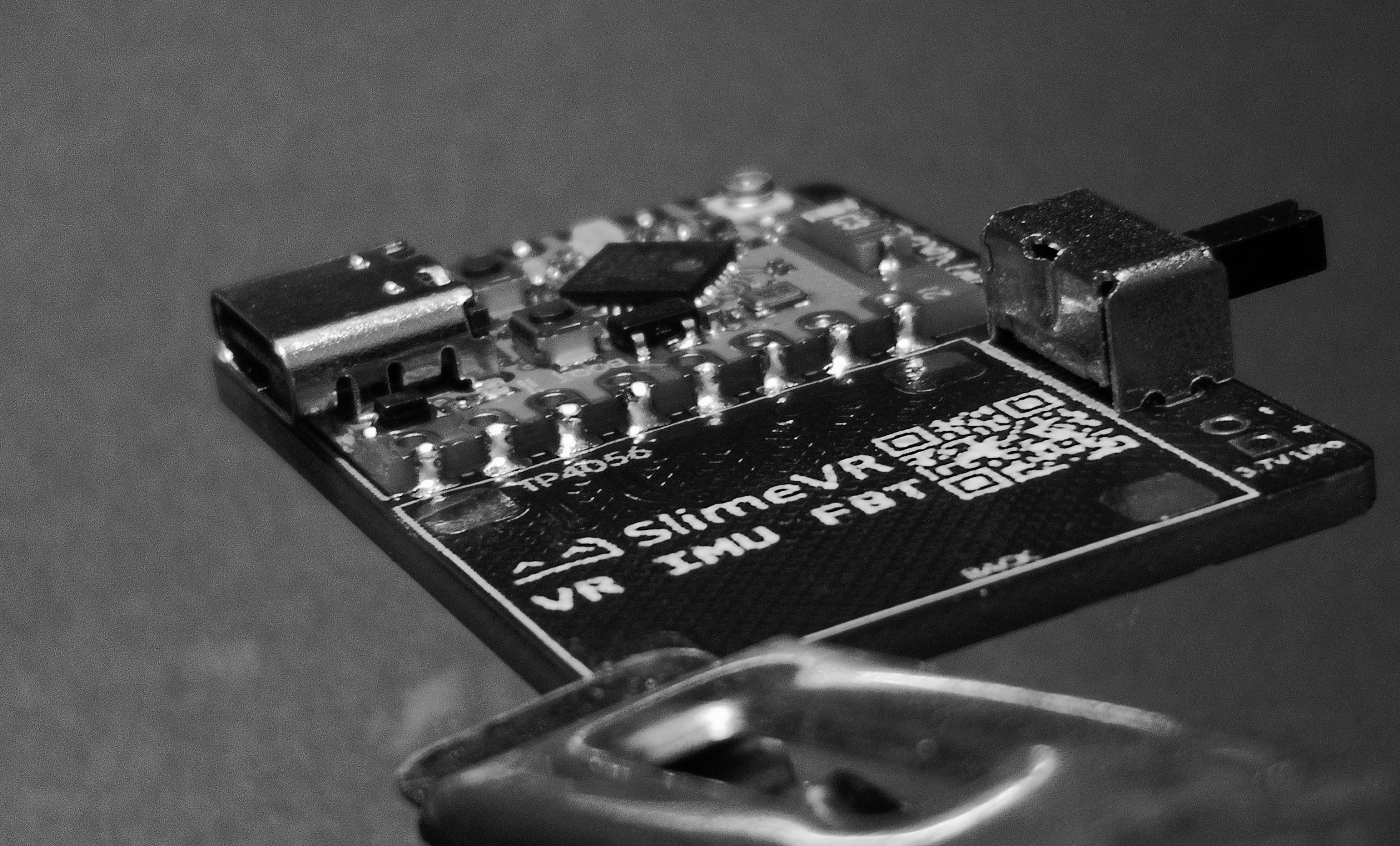
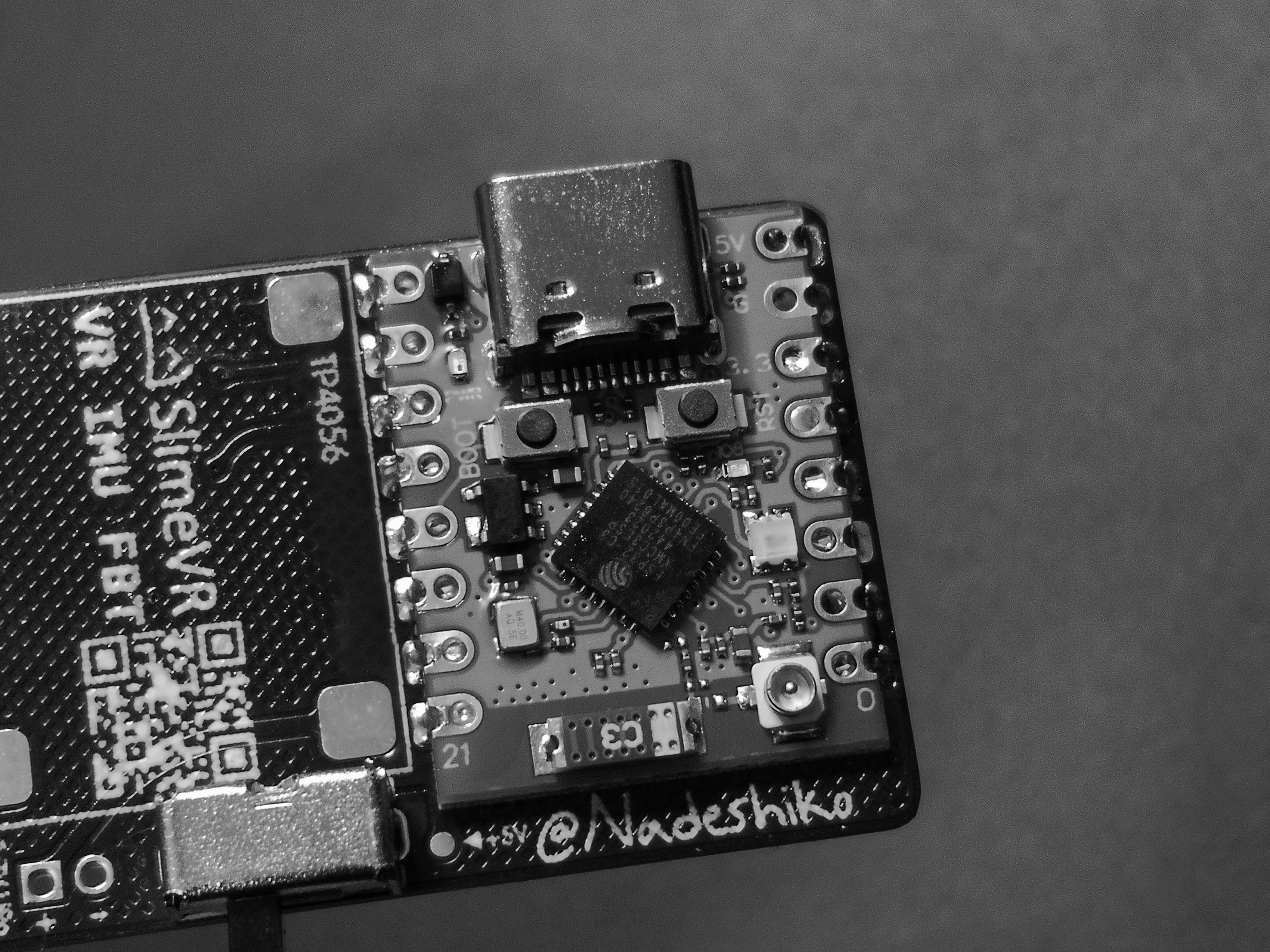
Soldering the C3 is same as the IMU earlier. Just slightly larger and few more pads. Start with fluxing the pads slightly.
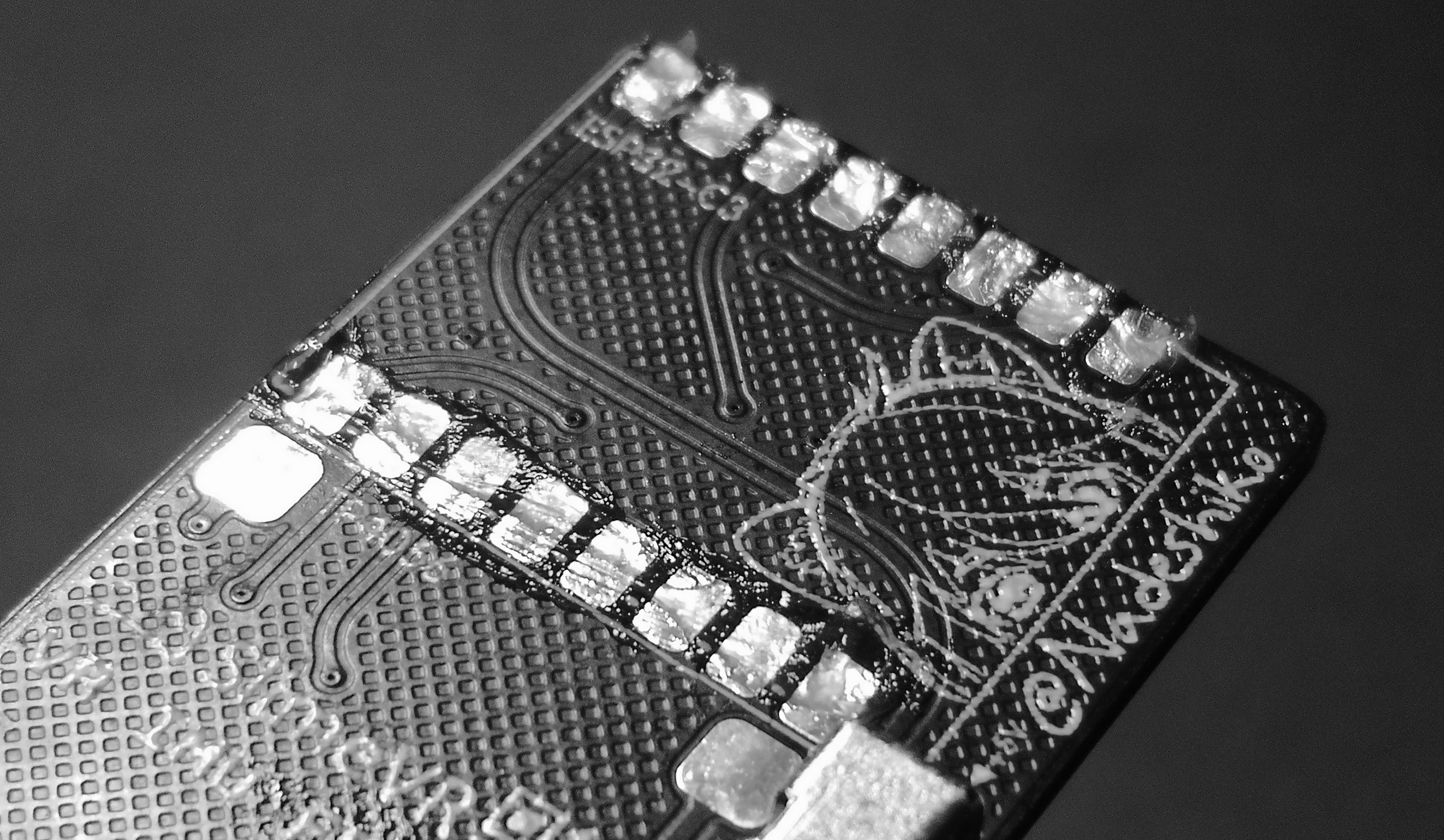
Clamp down the C3 with your solder helping hands in the correct position, lined up with the footprint on the PCB.
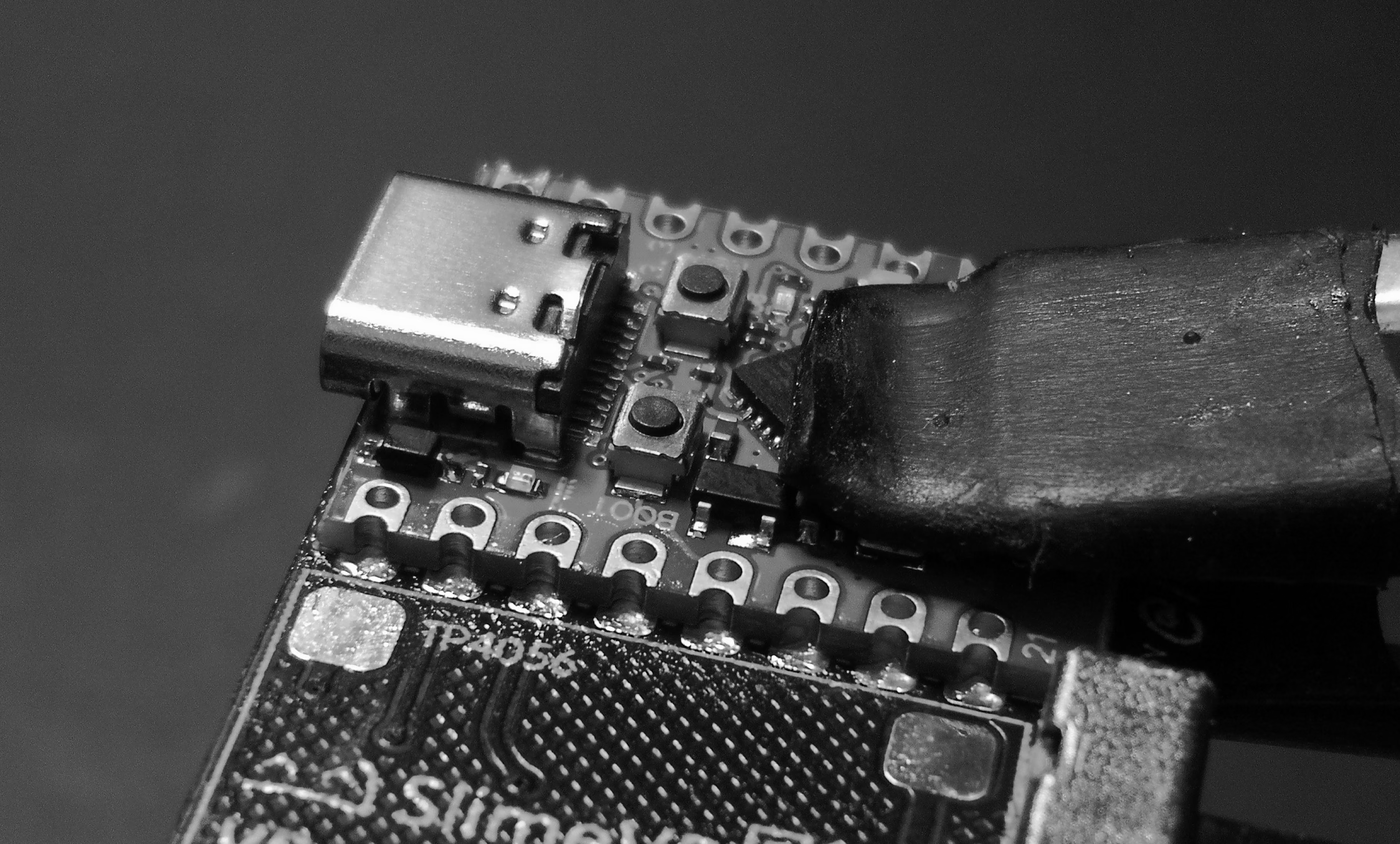
Solder the edge castellated holes of the C3, both left and right side, and double check visually to make sure there aren’t any missed pads.
Step 5 - TP4056 Unprotected Charger Module
The TP4056 3.7v Lithium battery charging module comes in many sizes and USB styles. You want the unprotected variant with 4 holes:
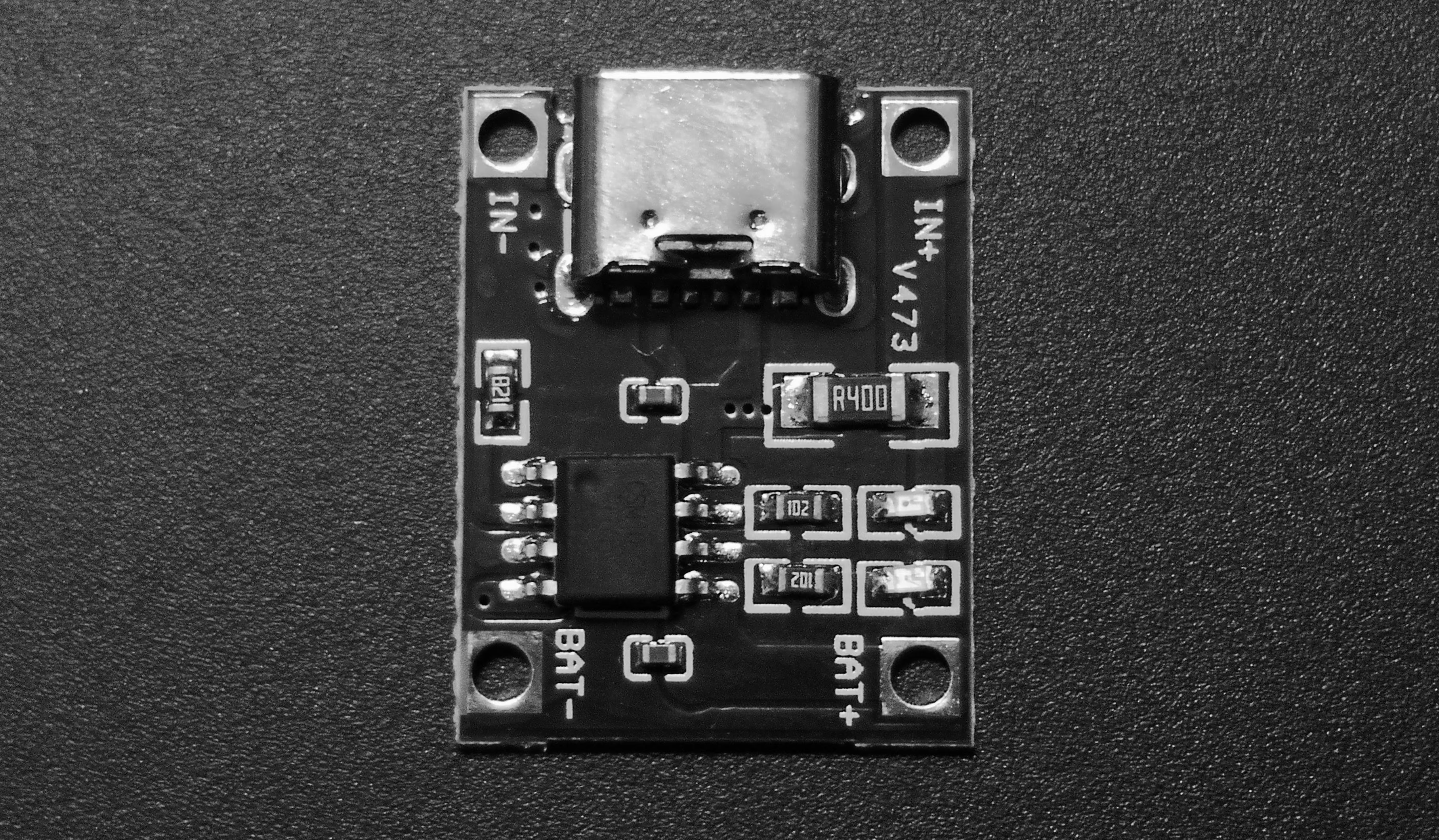
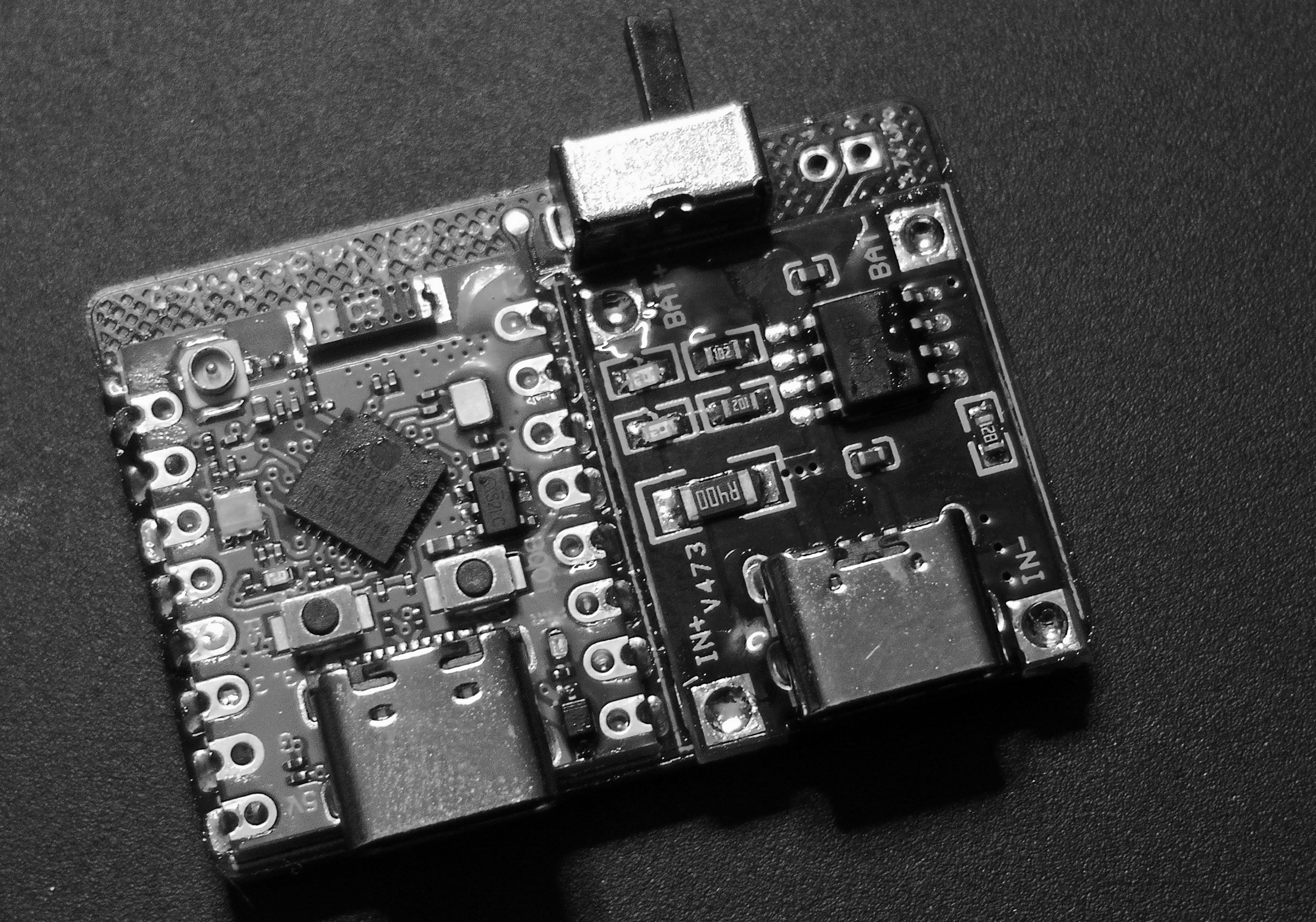
Flux the PCB pads and even some of the holes on the TP4056 just to make it easier to solder and then clamp it down.
It may not align with the footprint perfectly like mine, as these come with small variance in dimension between vendors.
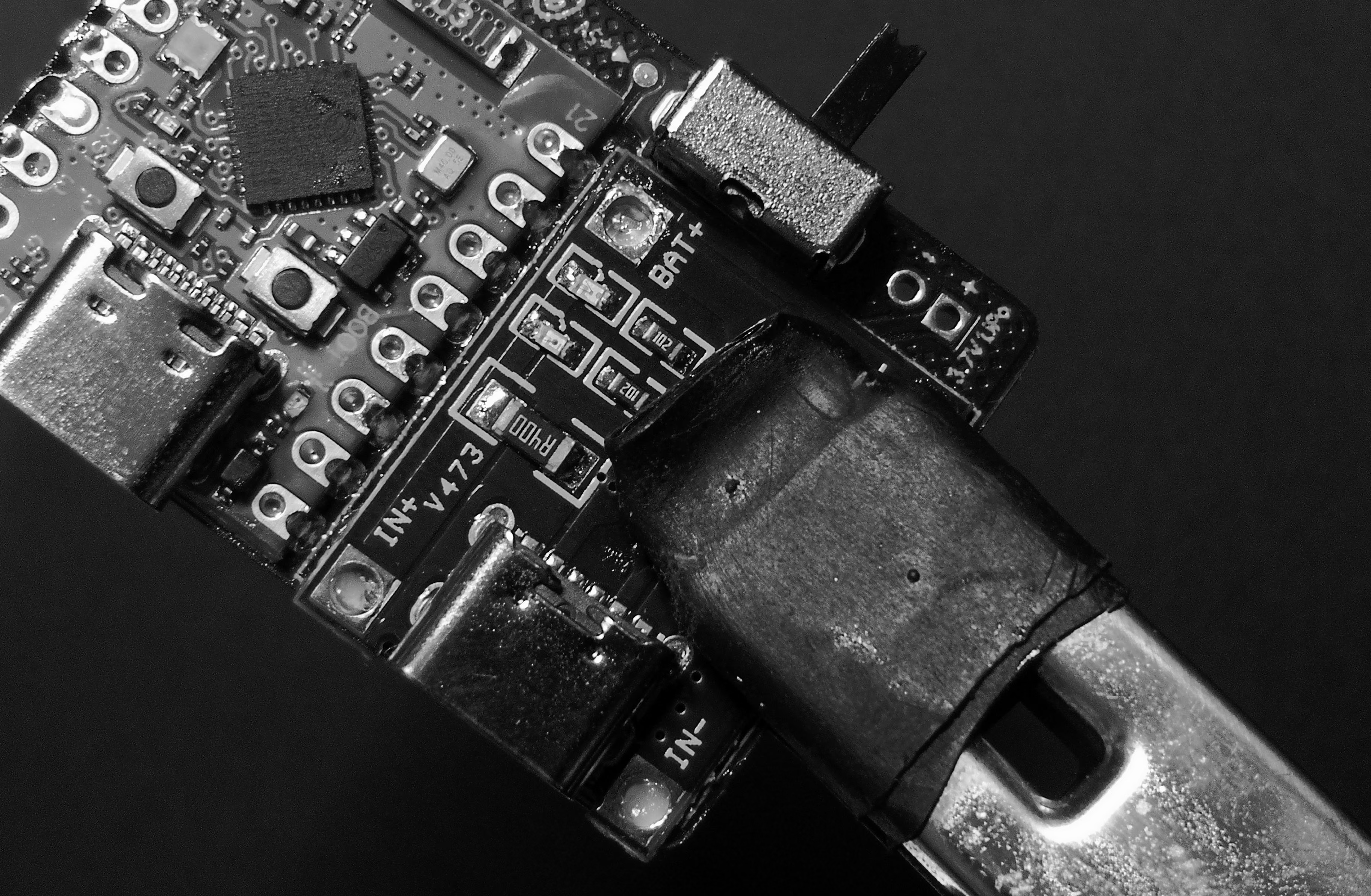
There may be a small overhang on the TP4056, mostly okay, but this can be filed/sanded down if it causes issues with fitment into the case.
Step 6 - 3.7v LiPo Battery
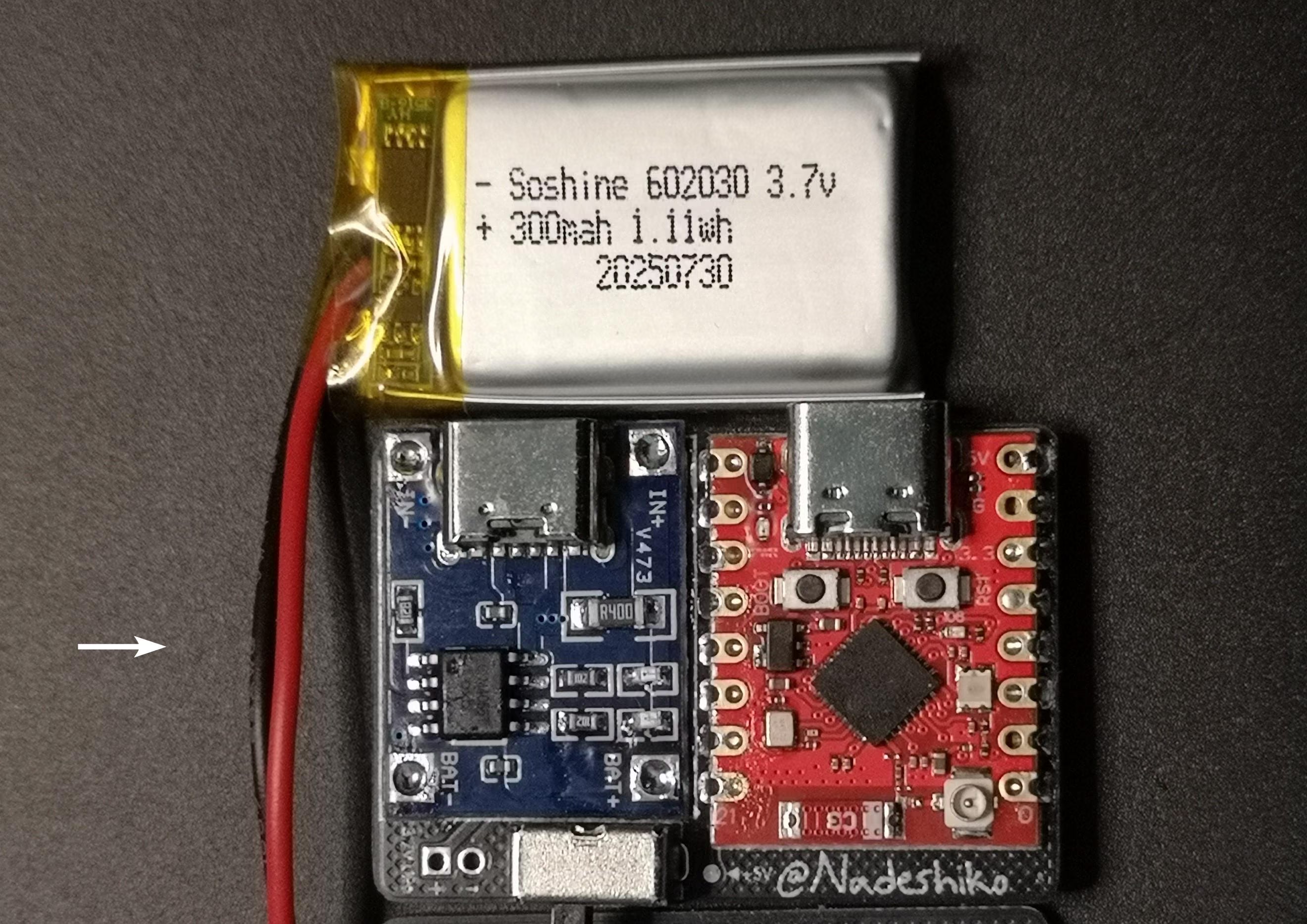
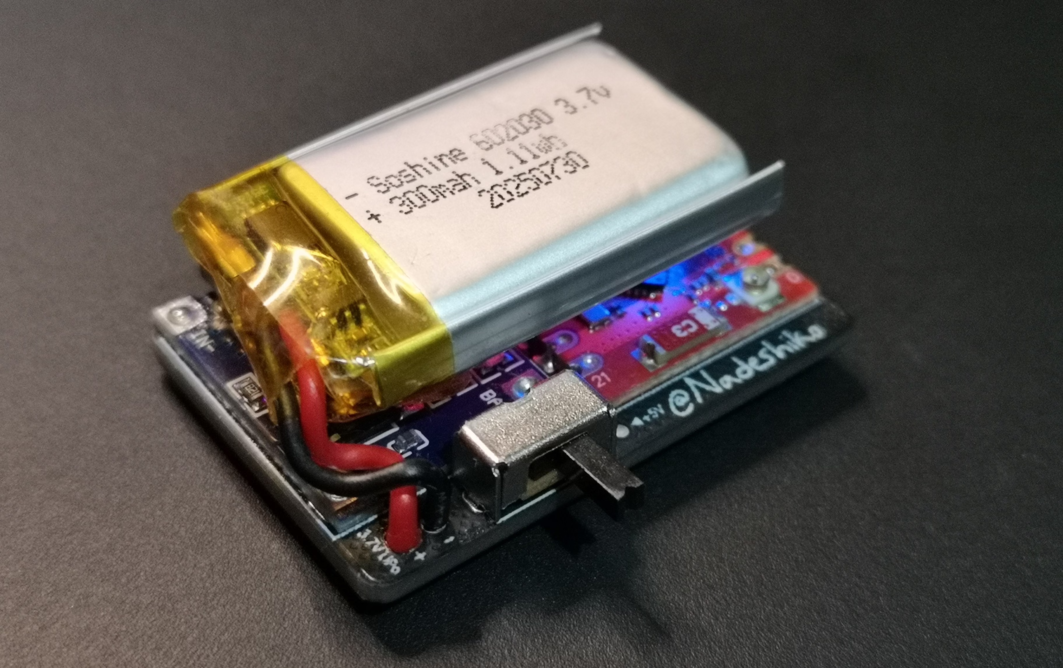
The tracker is basically complete and useable, and can be flashed right away. But we’ll continue this guide with the battery. I am using a 602030 battery here that I was able to find super cheap on AliExpress, which is 6mm x 20mm x 30mm as the name states. This Supermini PCB/Case SlimeVR can house up to a 6x25x40mm battery. Thicker batteries like 7mm could fit, but we need a gap between the battery and the inside wall of the case for the strap to pass through.
We need to cut the wire down as it’s arrives bit too long. Cut them short around where the arrow is indicated. For smaller batteries you might need a bit more wire, and less for larger batteries, so its fits in the case easier.
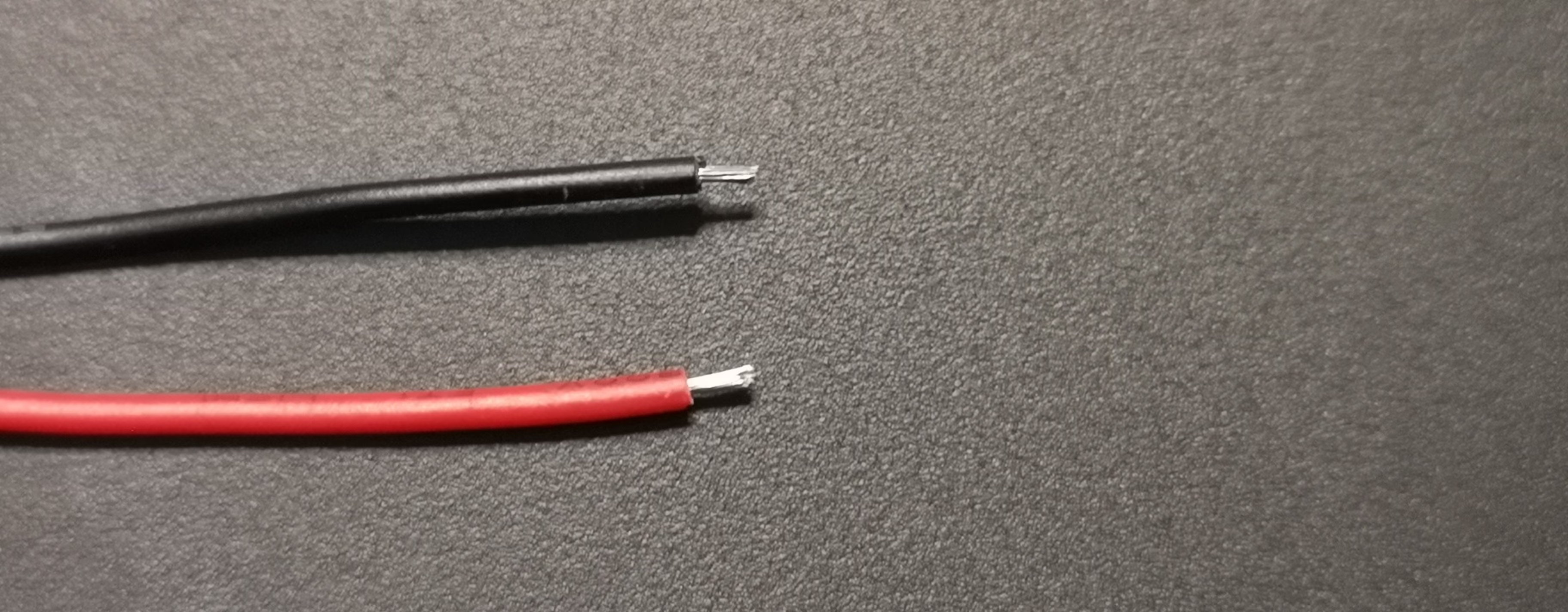
Strip the ends of the cable so we can solder it on the PCB.
Flux the cable ends and the +/- holes on the PCB and solder it up. Making sure it’s correct polarity.
The wires can be shaped/bent around, so the battery sits nicely on top of the modules/USB’s.
If wires too long you can redo it and cut it shorter. If too short, you can undo the yellow polyimide tape on the battery and redo the wires on it.
ESP32-C3 Supermini WiFi Antennas
There are two antenna modifications you can do to improve WiFi range and signal reliability on the ESP32-C3 Supermini V1 & V2. Both involve removing the stock C3 chip antenna.
Option A - IPEX Antenna (Plus/V2 variant only)
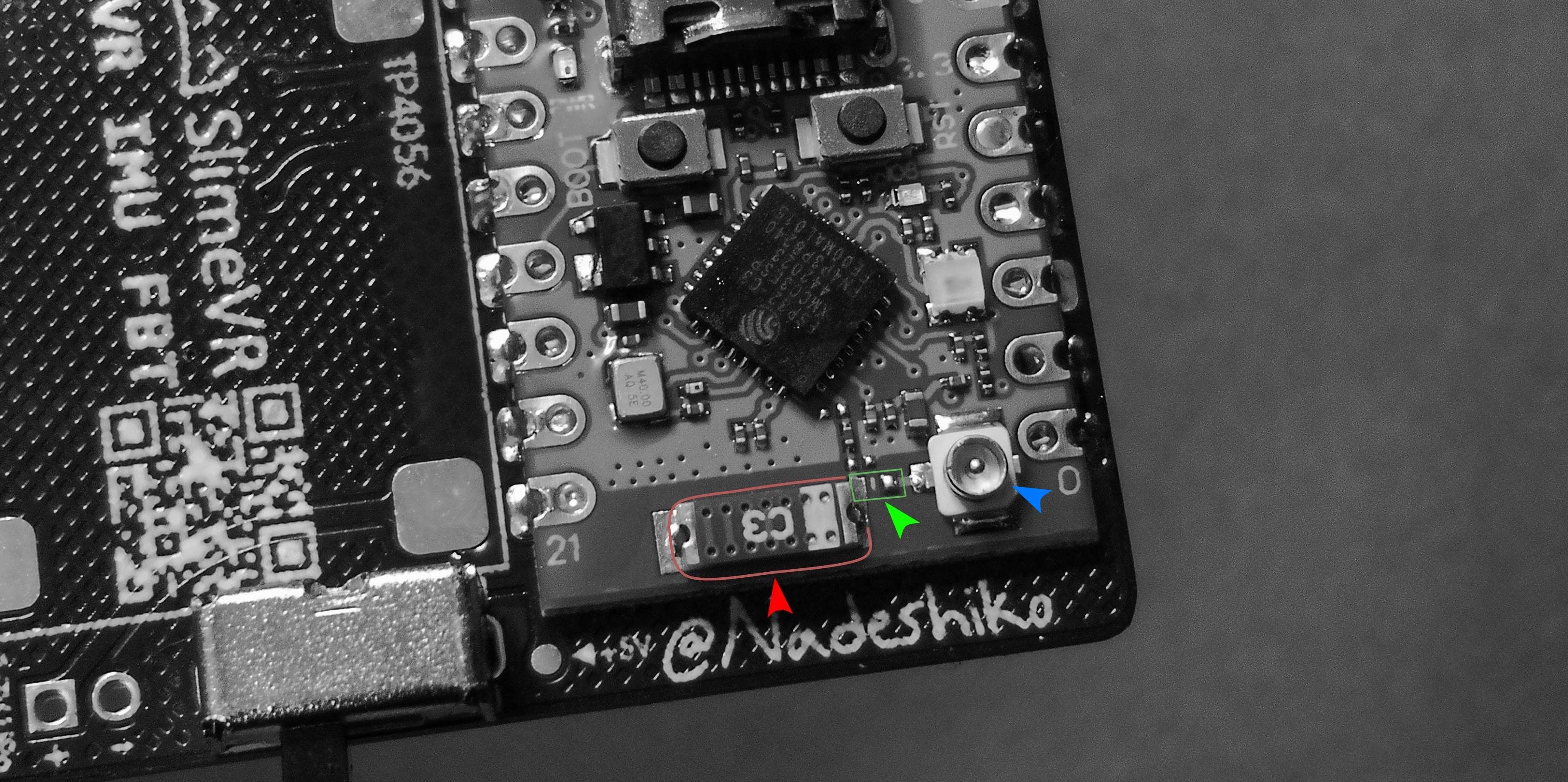
For the Plus/V2 variant C3 Supermini, you must solder a bridge between the two points marked with the green arrow to use the IPEX antenna.
This alone is enough to get the antenna to work, however the C3 chip antenna must be removed as it causes imperfect impedance matching and signal loss.
As some power leaks into the unused antenna, this reduces the efficiency and dB of the external antenna. For that, simply de-solder the red arrow marked C3 chip antenna, and then bridge green point with solder or a 0 Ohm resistor, and attach the IPEX antenna.
Option B - Quarter-Wave Wire Antenna (any C3 Supermini variant) - Recommended
Instead of using an IPEX antenna, you can solder a simple wire directly onto the C3 chip antenna’s main solder pad to create a Quarter-Wave () antenna. This works on any C3 Supermini variant and gives around 25 to 30 dBm signal strength gain over the stock chip antenna.
Why a wire antenna? The stock chip antenna on the C3 is compact but weak. A quarter-wave wire antenna is tuned to 2.4 GHz WiFi and naturally approaches the 50-ohm impedance the ESP32-C3’s radio is designed for, meaning more power goes into the air and less is reflected back into the ESP32 chip.
Wire length: Cut a piece of solid core wire to 31mm. This length comes from the quarter-wave formula adjusted for the velocity factor of copper wire:
Where c is the speed of light (~300,000 km/s), f is 2.45 GHz (center of the band), and K is the velocity factor (~0.96 for copper wire).
TIP
The extra ~1.5mm accounts for the solder joint which doesn’t radiate efficiently, the C-shape bending which creates stray capacitance that makes the antenna electrically shorter than its physical length, and the fact that WiFi spans 2.412 to 2.484 GHz so the true ideal length varies by channel. Starting slightly long and trimming is standard practice in RF, since you can always cut shorter but can’t add length back.
Steps:
- De-solder and remove the C3 chip antenna from the board.
- Cut a piece of wire to 31mm. Tin the wire with solder if it’s stranded so its one solid conductor.
- Solder the wire onto the chip antenna’s main solder pad.
- Bend the wire into a C shape so it loops back, forming a small circular loop. This shapes the radiation pattern into an omnidirectional “donut” and improves how the antenna couples with the board’s ground plane.
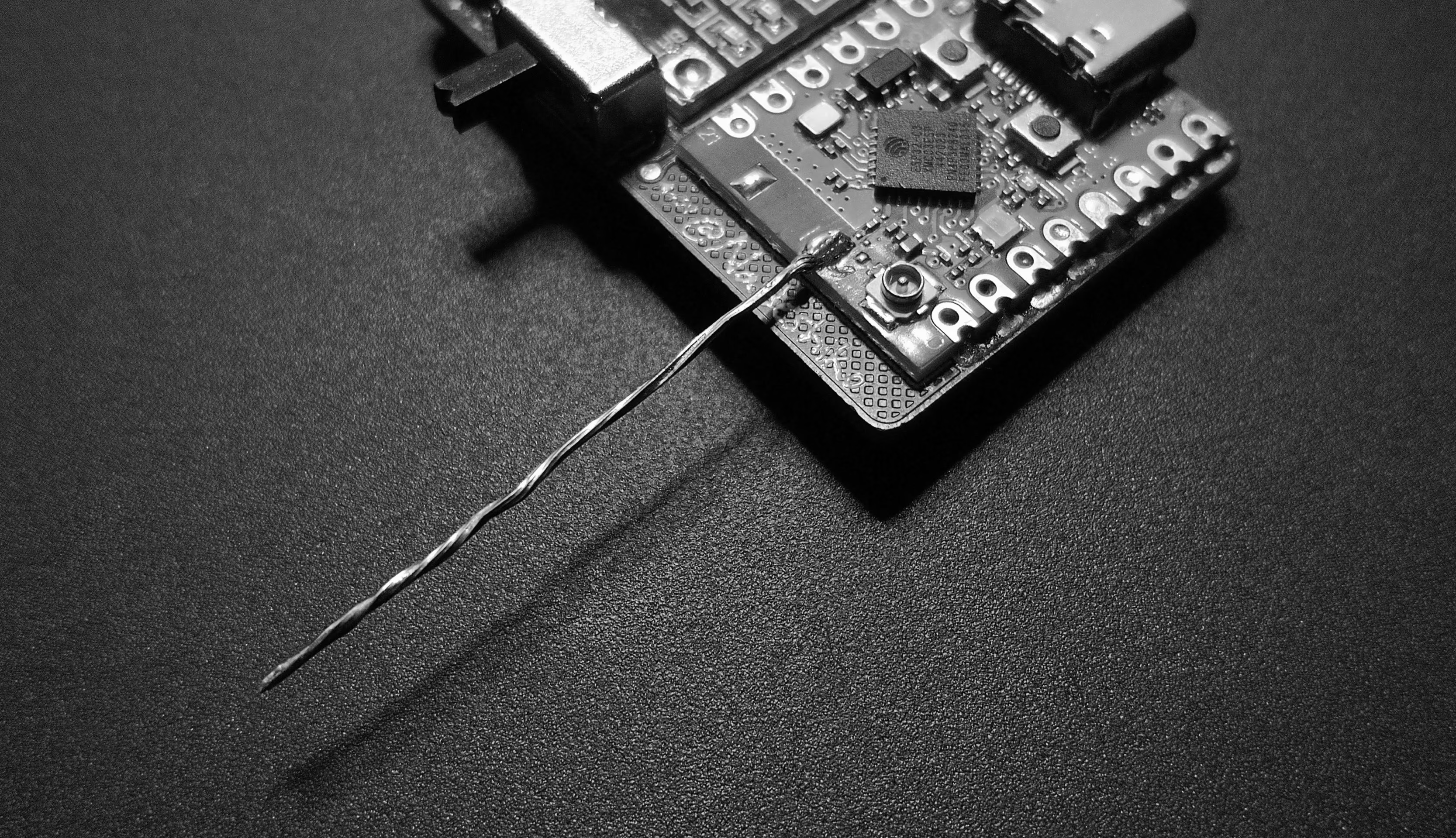
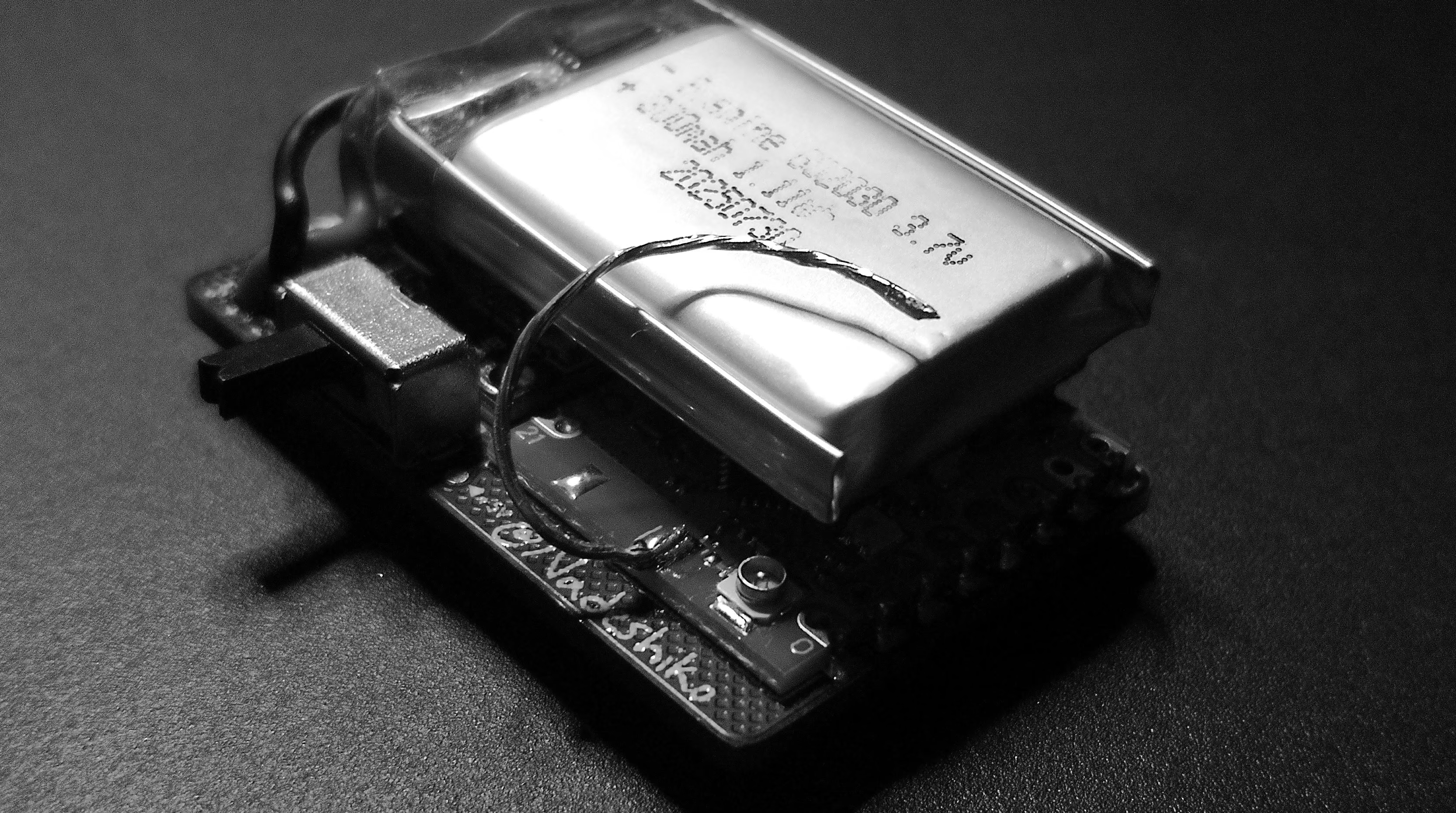
You can place the wire loop on either side of the PCB, but the backside (away from the battery) is ideal. On that side, the signal only has to pass through the case to reach your router. If it’s on the front side, the signal has to travel through the battery, PCB, and case. However you need to make sure it does not touch the PCB as the ground fill plane will affect the signal:
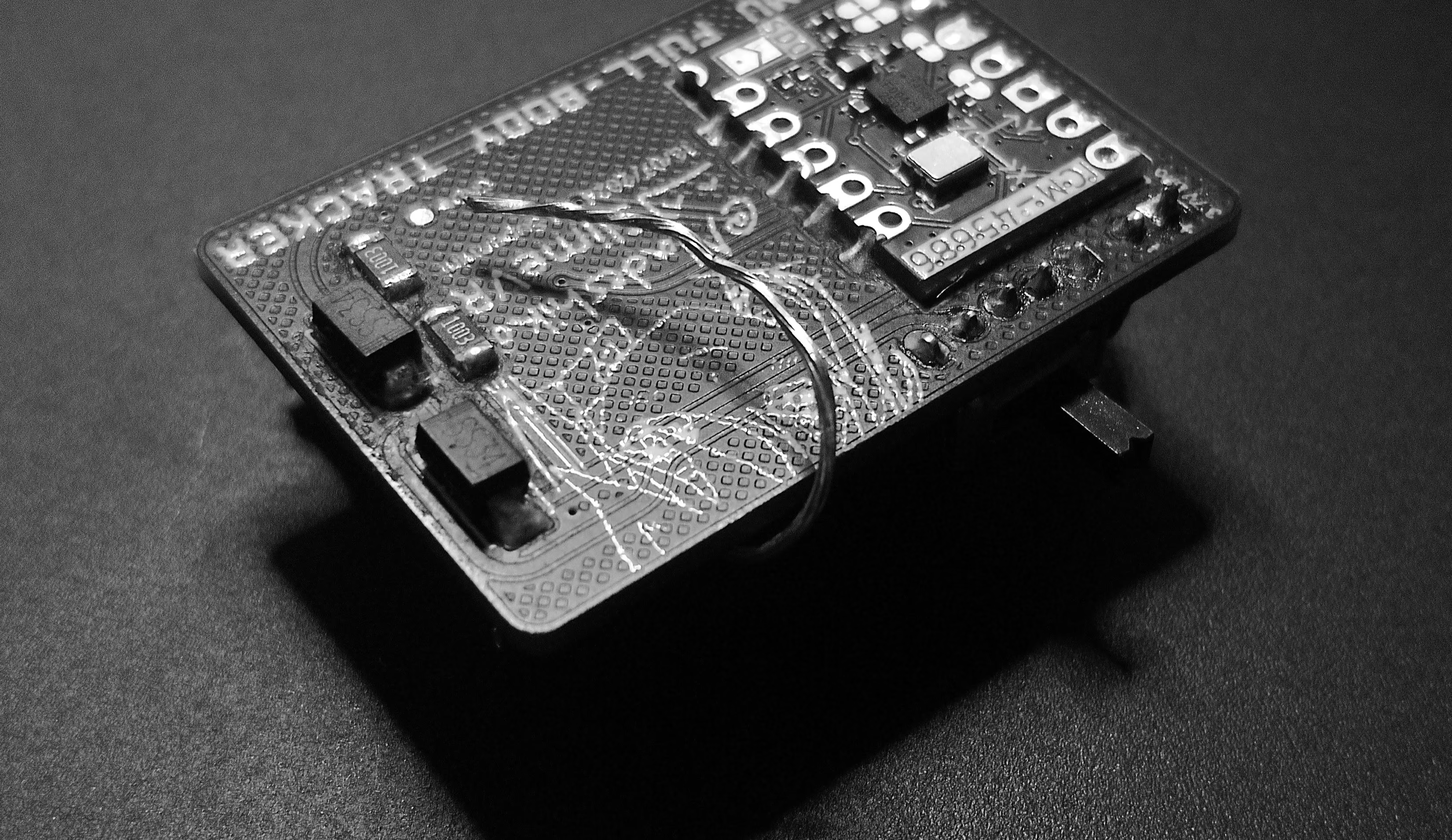
TIP
Solid core wire is ideal, but you can also use the offcut from the battery cable. Tin it thoroughly with solder so the strands fuse into a single rigid conductor. Tinning gives the wire a smoother outer surface which is better for RF at 2.4 GHz (due to the skin effect), and makes it stiff enough to hold the C shape without shifting and detuning the antenna.
Why a C shape? If you leave the wire straight instead of doing a loop/U/C, the signal becomes more directional like a water hose pointing in one direction rather than spraying evenly around you and the tracker may lose connection depending on which way your body is facing relative to your router.
NOTE
Despite being a manufactured antenna, the IPEX ESP32-C3 Supermini Plus/V2 actually underperforms compared to the wire antenna (Option B). The U.FL connector and coaxial cable introduce signal loss at 2.4 GHz, and the IPEX antenna expects a ground plane. The wire antenna avoids all of this. It’s a full quarter-wave element with a direct solder connection and zero cable loss.
Flashing
Flashing these Slimes is the same as flashing Gorbit99’s Tiny Slime. I will show you how to flash it directly from the SlimeVR server and the online firmware flash tool, and how to solve any flashing or WiFi setup issues you may run into.
NOTE
For the online firmware flash tool, you can follow this link with everything already inputted for the flashing. You just need to change the firmware version and select your primary IMU type.
Flashing with the online firmware tool
- You want to be on the latest firmware in the drop down selection.
- For the board type, you want to choose
BOARD_LOLIN_C3_MINI. - Open Advanced Options, change SDA Pin to
6, SCL Pin to7, INT Pin to5, and LED Pin to8. - For Primary IMU, select the one you have.
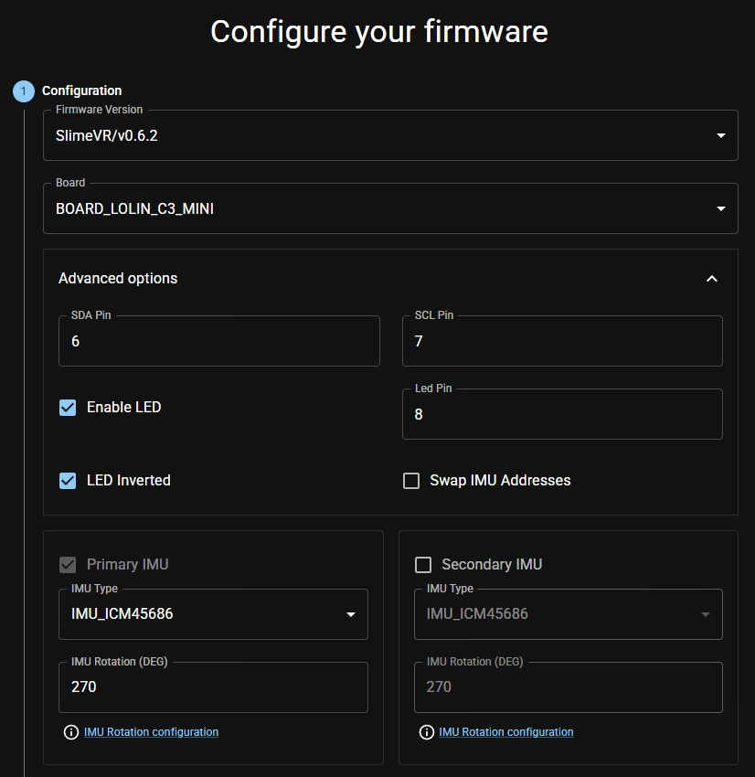
Next we do the Battery Sense settings.
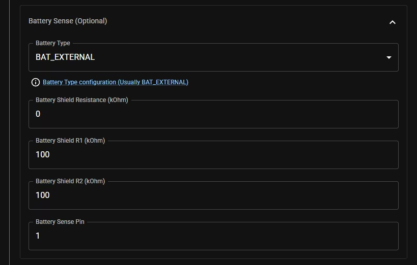
- Click open Battery Sense (optional) section, select Battery Type as
BAT_EXTERNAL. - Change Battery Shield Resistance (kOhm) put
0. - Set Battery Shield (kOhm) to
100for both Battery Shield R1 and R2. - For Battery Sense Pin set to pin
1.
Open the Wi-Fi settings section and input your 2.4GHz Wi-Fi credentials.
Now on the Supermini. Set it to flashable mode, first double check that it’s turned off at the switch, Hold down the left button on it labeled “BOOT”, and while holding it down, plug it into your PC.
After flashing you need to manually reset the Supermini. This can be done by either hitting the reset button labeled “RST” or by just unplugging it and powering it on.
If everything went well and your SlimeVR server is turned on, it should be able to connect and appear in there.
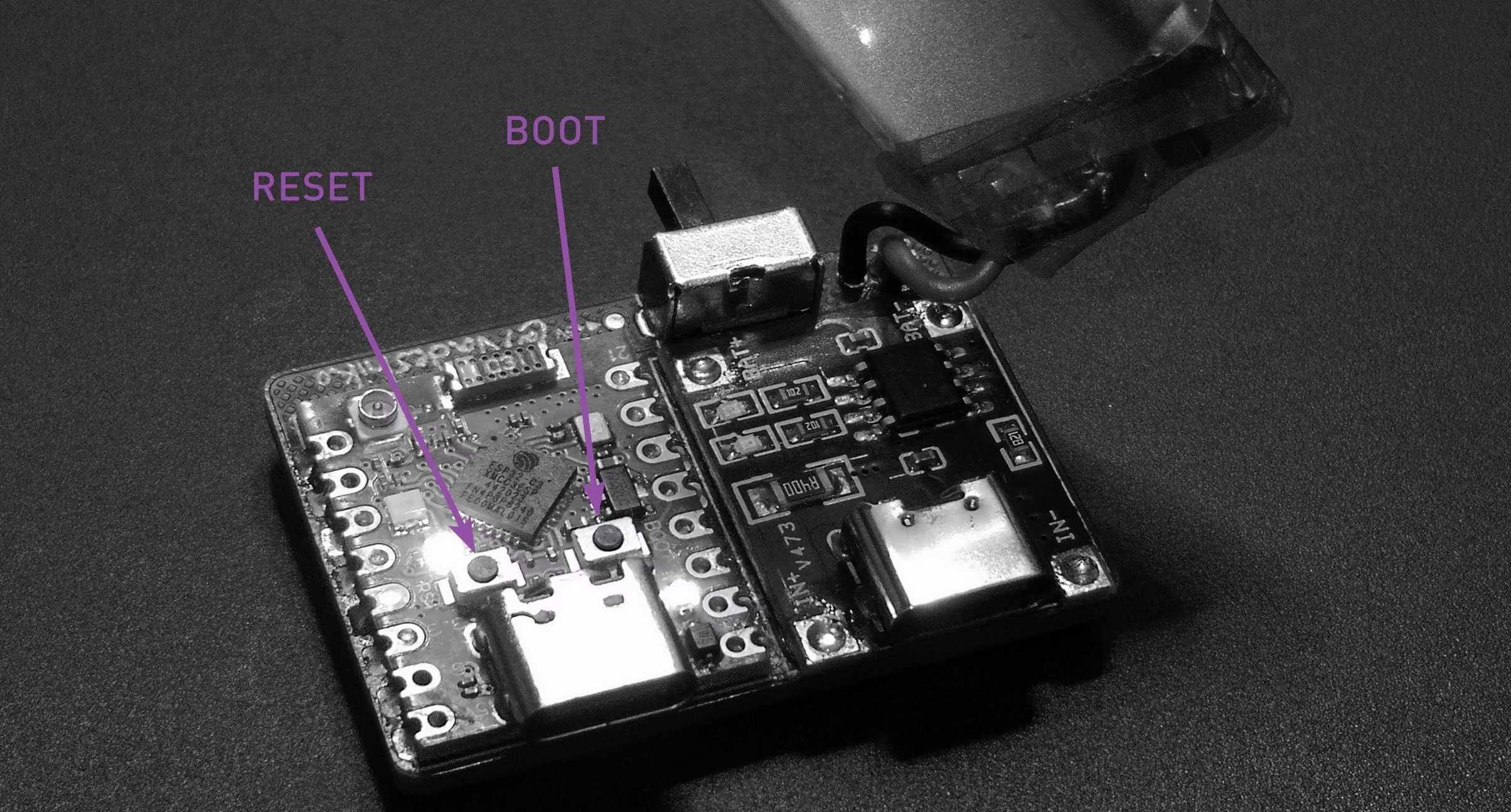
NOTE
Another flash mode method is by holding the “BOOT” button, click the “RST” and then release “BOOT” button
If however it doesn’t appear in the SlimeVR server and nothing is showing in the server’s serial console, you can use this Online Serial Terminal with the SlimeVR server closed.
Use the serial console if it doesn’t appear to connect to WiFi, forgot to set WiFi credentials when flashing, or tracker works over USB but not over WiFi.
Use the serial command SET WIFI XXXX YYYY where XXXX is your 2.4GHz name, and YYYY is the password, both are case sensitive.
For everything else, use the SlimeVR Documentation, as it contains information for proper SlimeVR server setup, calibration, and wearing.
Sometimes flashing the latest firmware might not work at all on the C3 Supermini’s and certain IMU combos. Thus you can try older versions such as 0.6.2 with VSCode flashing method and then upgrade it to latest through the SlimeVR server afterwards.
Resources
Useful Links:
- SlimeVR Documentation
- SlimeVR Github
- SlimeVR Discord
- Online Firmware Flasher
- Online Firmware Flasher Alt
- SlimeVR-Tracker-ESP
- SlimeVR-Server
Ordering
PCB
Ordering the PCB and 3D Prints is easy. Head to the releases section and download the 3D print .stl files, and the PCB Gerber .zip files.
For PCB ordering, head over to JLCPCB and upload the gerber .zip files. Use the settings below on the order page.
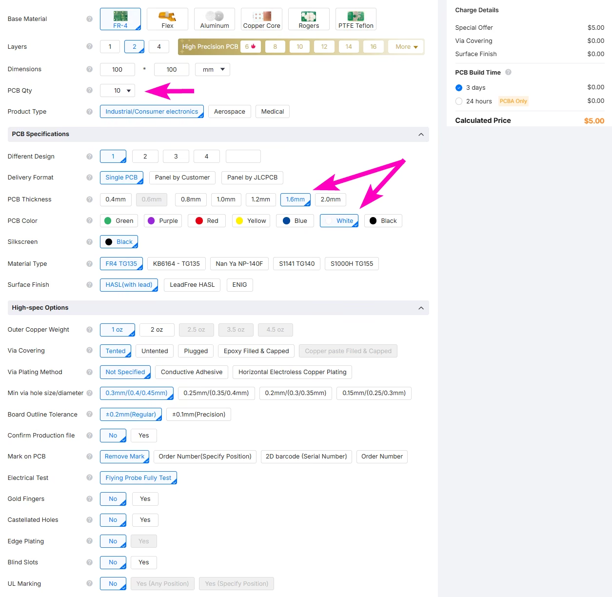
They can also be ordered from your preferred PCB manufacturer.
Cases
For 3D Print case ordering, head over to JLC3DP and upload the .stl files for each model, including the top/body and base/end cap etc. One case comes in two parts, so make sure you upload both halves. Then use the settings below on the order page and set the quantity of each part to the number of trackers you are building. The available SLA material and prices will vary, as the model has been designed to be used with any of the SLA resins, any of the cheapest options will be good enough for the trackers, typically the opaques are the best. I recommend the 9000HE. You will get a warning of printing risk, such as walls being too thin in a certain spot, this can be ignored and is done by design intention.
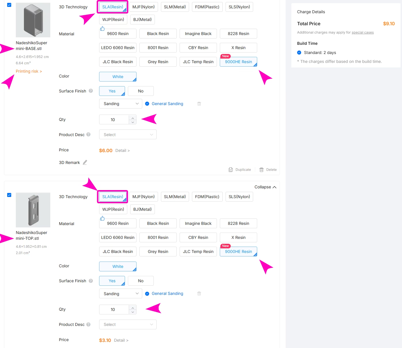
Cases can also be ordered from your preferred 3D print services.
Support
If you are unsure of an assembly or flashing step, you can always reach out to me on Discord.
@aeurias, or add on VRChat: Nadeshiko ~.
License
Copyright Nadeshiko 2023.This source describes Open Hardware and is licensed under the CERN-OHL-W v2.
You may redistribute and modify this documentation and make products using it under the terms of the CERN-OHL-W v2 (https://cern.ch/cern-ohl) .
This documentation is distributed WITHOUT ANY EXPRESS OR IMPLIED WARRANTY, INCLUDING OF MERCHANTABILITY, SATISFACTORY QUALITY AND FITNESS FOR A PARTICULAR PURPOSE. Please see the CERN-OHL-W v2 for applicable conditions.
Source location: https://github.com/Aeurias/NadeshikoSlimeVR
As per CERN-OHL-W v2 section 4.1, should You produce hardware based on these sources, You must maintain the Source Location visible on the PCB of the @Nadeshiko SlimeVR tracker or other product you make using this documentation.